Chapter 2 Hardware Overview of the NI 78xxR
R Series Intelligent DAQ User Manual 2-14 ni.com
Use DIFF input connections for greater signal integrity for any input signal
that does not meet the preceding conditions.
You can configure the NI 783xR/784xR/785xR channels in software for
RSE or NRSE input modes. Use the RSE input mode for floating signal
sources. In this case, the NI 783xR/784xR/785xR provides the reference
ground point for the external signal. Use the NRSE input mode for
ground-referenced signal sources. In this case, the external signal supplies
its own reference ground point and the NI 783xR/784xR/785xR should not
supply one.
In single-ended input modes, electrostatic and magnetic noise couples into
the signal connections more than in differential input modes. The coupling
is the result of differences in the signal path. Magnetic coupling
is proportional to the area between the two signal conductors. Electrical
coupling is a function of how much the electric field differs between the
two conductors.
Single-Ended Connections for Floating Signal
Sources (RSE Input Mode)
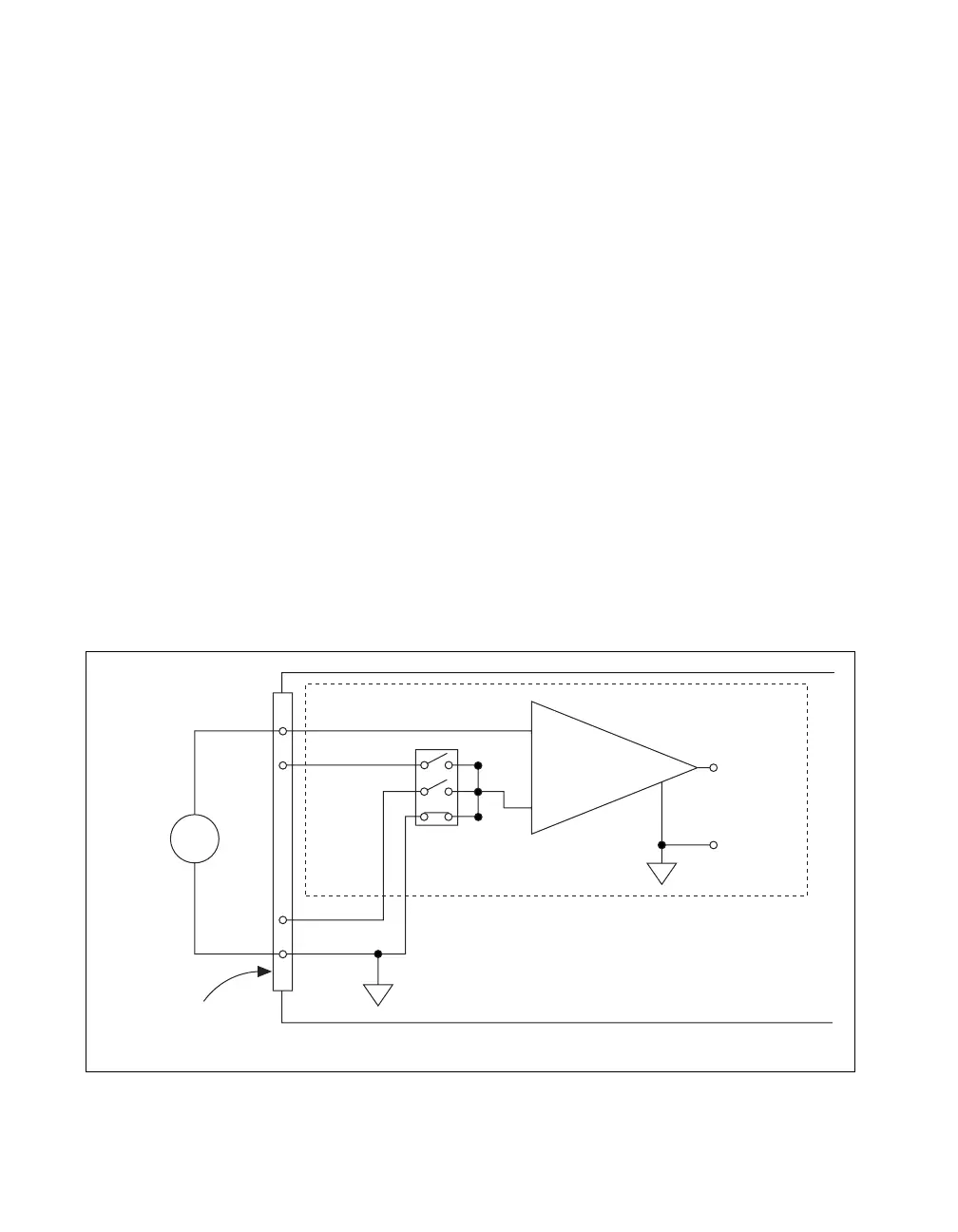
Figure 2-8 shows how to connect a floating signal source to a channel on
the NI 783xR/784xR/785xR configured for RSE input mode.
Figure 2-8. Single-Ended Input Connections for Nonreferenced or Floating Signals
–
+
–
+
–
+
I/O Connector
AISENSE
AIGND
V
m
AI+
AI–
V
s
Floating
Signal
Source
Instrumentation
Amplifier
Measured
Voltage
RSE Input Mode Selected
 Loading...


