b) Align the sbRIO-9687 with the M3 x 43.36, M-F standoffs and the four M3 x 11.12,
M-F standoffs.
c) Seat the sbRIO-9687 connectors and the sbRIO-9683 or sbRIO-9684 connectors to
connect the boards.
d) Insert and tighten M3 x 5 panhead screws through the sbRIO-9687 to the installed
M3 x 43.36, M-F standoffs and to the M3 x 11.12, M-F standoffs.
e) Connect the CAN input cable and the RS232 input cable to sbRIO-9687 connectors
J1 and J2, respectively.
f) Connect the power cable between the sbRIO-9687 and the sbRIO-9607.
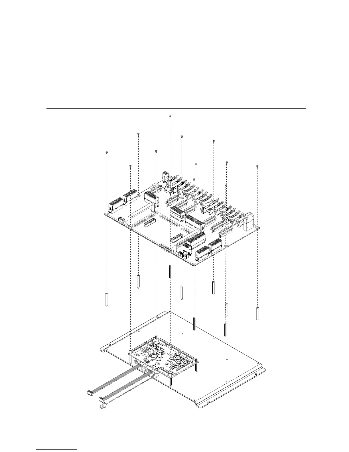
Figure 7. Mating the sbRIO-9687 to the sbRIO-9683 or sbRIO-9684
10 | ni.com | sbRIO-9687 Getting Started Guide
 Loading...


