Power-On States
At system startup and reset, the hardware sets all DIO lines to high-impedance inputs. The
DAQ device does not drive the signal high or low. Each line has a weak pull-up resistor
connected to it.
P2.7/PFI 0 Event Counter
You can configure P2.7/PFI 0 as the source for a 32-bit counter. In this mode, the device
counts high to low transitions on P2.7/PFI 0. The counter can be armed and disarmed and the
count can be read or reset through software. Refer to your software documentation for more
information about counter programming techniques.
+5 V Power Source
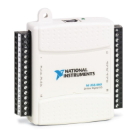
The NI USB-6501 supplies a nominal 5 V from two pins, one on each screw terminal block.
The voltage source is provided by the USB host. The voltage is nominally 5 V but varies from
system to system. Refer to the NI USB-6501 Device Specifications for more information about
USB bus power specifications. This source can be used to power external components.
Note Output is disabled when the device is in USB suspend.
Caution When using the 5 V source, understand the current requirements of the
load connected. Do not exceed the specified limits of the +5 V output current
specification.
Where to Go from Here
This section lists where you can find example programs and additional documentation for the
NI USB-6501.
Example Programs
The NI-DAQmx and NI-DAQmx Base software includes examples you can use to get started
programming with your device. Examples are also available from ni.com/support. Modify
example code and save it in an application, use examples to develop a new application, or add
example code to an existing application.
NI-DAQmx Example Programs
NI-DAQmx examples are available on the software media and from ni.com/support. To run
examples without the device installed, use an NI-DAQmx simulated device. For more
information, in Measurement & Automation Explorer (MAX), select Help»Help Topics»NI-
DAQmx»MAX Help for NI-DAQmx and search for simulated devices.
NI USB-6501 User Guide | © National Instruments | 11
 Loading...
