Table 2. Signal Descriptions (Continued)
Signal Name Direction Description
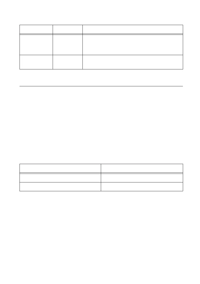
+5 V Output The voltage source provided by the USB host. The
voltage is nominally 5 V, but varies from system to
system.
GND — Ground: The reference for the digital signals and the
+5 VDC supply.
Digital I/O
The NI USB-6501 device has 24 single-ended digital lines that comprise the three DIO ports:
P0.<0..7>, P1.<0..7>, and P2.<0..7>. P2.7/PFI 0 can also function as a 32-bit event counter.
Static DIO
Each DIO line can be individually programmed as a static DI or DO line. You can use static
DIO lines to monitor or control digital signals. All samples of static DI lines and updates of
DO lines are software-timed.
Digital Output
The following table shows the correlation between terminology used for hardware
functionality and for NI-DAQmx.
Table 3. Hardware and NI-DAQmx Terminology
Hardware Functionality NI-DAQmx Terminology
Open-drain Open collector
Push-pull Active drive
The default configuration of the NI USB-6501 DIO ports is open collector, allowing 5 V
operation, with an onboard 4.7 kΩ pull-up resistor. An external, user-provided pull-up resistor
can be added to increase the source current drive up to a 8.5 mA limit per line, as shown in the
following figure.
8 | ni.com | NI USB-6501 User Guide

 Loading...


