If you are unsure which thermocouple lead is positive and which is negative, refer to the
thermocouple documentation or the thermocouple wire spool.
Figure 5. Connecting a Thermocouple Input Signal to the NI USB-TC01
For best results, NI recommends using insulated or ungrounded thermocouples when possible.
If you need to increase the length of your thermocouple, use the same type of thermocouple
wires to minimize the error introduced by thermal EMFs.
Temperature measurement errors depend in part on the thermocouple type, the temperature
being measured, the accuracy of the thermocouple, and the cold-junction temperature. Error
graphs for each thermocouple type connected to the NI USB-TC01 are provided in the
NI USB-TC01 Device Specifications document, available at ni.com/manuals.
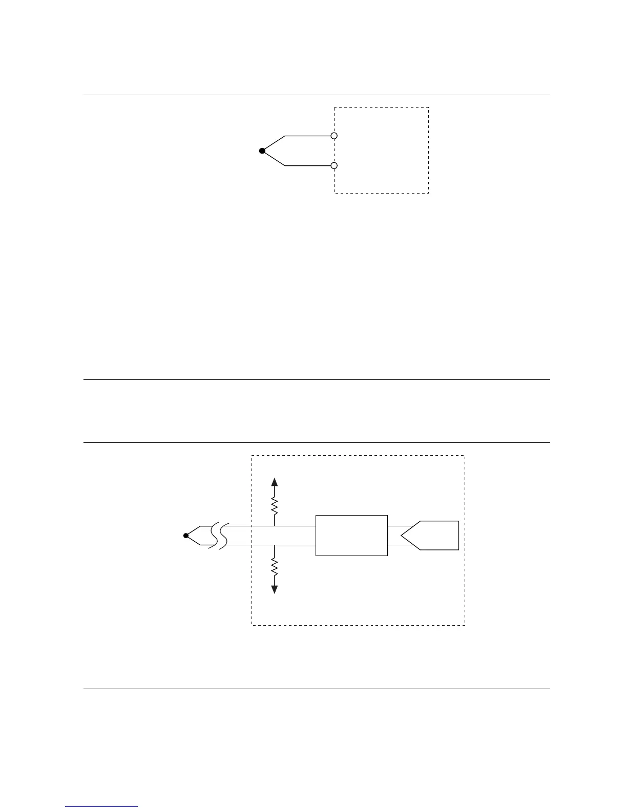
NI USB-TC01 Circuitry
The NI USB-TC01 device’s thermocouple channel passes through a differential filter and is
sampled by a 20-bit analog-to-digital converter (ADC), as shown in the following figure.
Figure 6. NI USB-TC01 Input Circuitry
Thermocouple Measurement Accuracy
Temperature measurement errors depend in part on the thermocouple type, the temperature
being measured, the accuracy of the thermocouple, and the cold-junction temperature sensing
accuracy.
6 | ni.com | NI USB-TC01 User Guide

 Loading...


