Table 6. NI USRP-2920 Module LEDs (Continued)
LED Indication
C Indicates the receive status of the module:
OFF—The module is not receiving data.
GREEN—The module is receiving data.
D Indicates the firmware status of the module:
OFF—The firmware is not loaded.
GREEN—The firmware is loaded.
E Indicates the reference lock status of the LO on the module:
OFF—There is no reference signal, or the LO is not locked to a reference signal.
BLINKING—The LO is not locked to a reference signal.
GREEN—The LO is locked to a reference signal.
F Indicates the power status of the module:
OFF—The module is powered off.
GREEN—The module is powered on.
NI USRP-2921
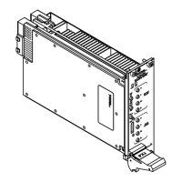
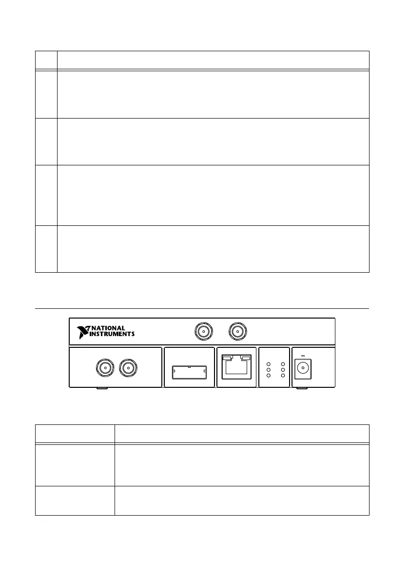
Figure 2. NI USRP-2921 Front Panel
MIMO EXPANSION GB ETHERNET POWER
RX 1
TX 1
REF IN PPS IN
A
C
E
B
D
F
NI USRP
-
2921
2.4 - 2.5 GHz, 4.9 - 5.85 GHz
RX 2
TX 2
6 V 3 A
Table 7. NI USRP-2921 Module Front Panel Connectors
Connector Use
RX 1
TX 1
Input and output terminal for the RF signal. RX 1 TX 1 is an SMA (f)
connector with an impedance of 50 Ω and is a single-ended input or
output channel.
RX 2 Input terminal for the RF signal. RX 2 is an SMA (f) connector with
an impedance of 50 Ω and is a single-ended input channel.
NI USRP-2920/2921/2922 Getting Started Guide | © National Instruments | 15
 Loading...