Table 8. NI USRP-2921 Module LEDs (Continued)
LED Indication
E Indicates the reference lock status of the LO on the module:
OFF—There is no reference signal, or the LO is not locked to a reference signal.
BLINKING—The LO is not locked to a reference signal.
GREEN—The LO is locked to a reference signal.
F Indicates the power status of the module:
OFF—The module is powered off.
GREEN—The module is powered on.
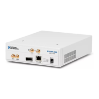
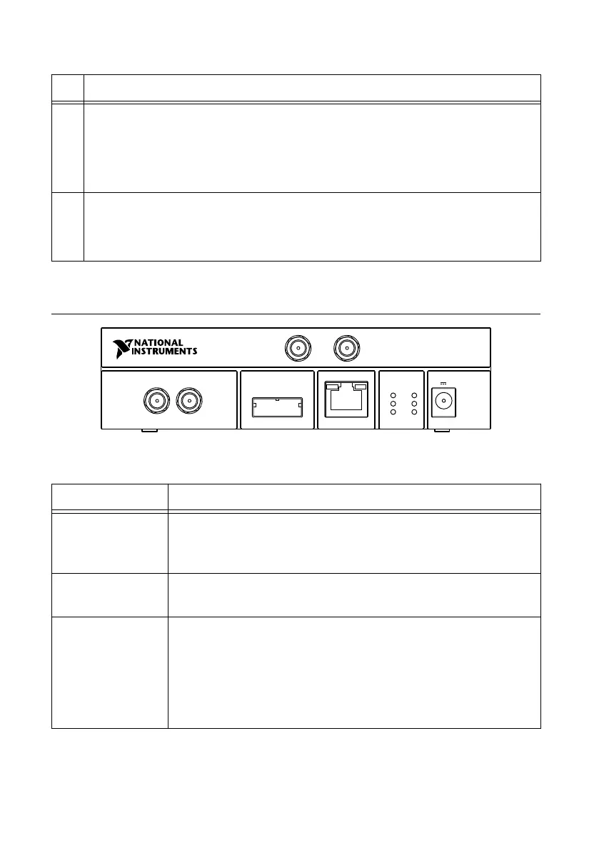
NI USRP-2922
Figure 3. NI USRP-2922 Front Panel
MIMO EXPANSION GB ETHERNET
RX 1
TX 1
REF IN PPS IN
A
C
E
B
D
F
NI USRP
-
2922
400 MHz - 4.4 GHz
RX 2
POWER
6 V 3 A
Table 9. NI USRP-2922 Module Front Panel Connectors
Connector Use
RX 1
TX 1
Input and output terminal for the RF signal. RX 1 TX 1 is an SMA (f)
connector with an impedance of 50 Ω and is a single-ended input or
output channel.
RX 2 Input terminal for the RF signal. RX 2 is an SMA (f) connector with
an impedance of 50 Ω and is a single-ended input channel.
REF IN Input terminal for an external reference signal for the local oscillator
(LO) on the device. REF IN is an SMA (f) connector with an
impedance of 50 Ω and is a single-ended reference input. REF IN
accepts a 10 MHz signal with a minimum input power of 0 dBm
(.632 Vpk-pk) and a maximum input power of 15 dBm (3.56 Vpk-pk)
for a square wave or sine wave.
NI USRP-2920/2921/2922 Getting Started Guide | © National Instruments | 17
 Loading...