Table 14. NI USRP-2932 Module Front Panel Connectors (Continued)
Connector Use
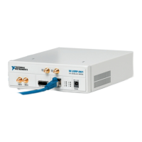
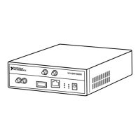
GB ETHERNET The gigabit Ethernet port accepts an RJ-45 connector and gigabit
Ethernet compatible cable (Category 5, Category 5e, or Category 6).
POWER The power input accepts a 6 V, 3 A external DC power connector.
Table 15. NI USRP-2932 Module LEDs
LED Indication
A Indicates the transmit status of the module:
OFF—The module is not transmitting data.
GREEN—The module is transmitting data.
B Indicates the status of the physical MIMO cable link:
OFF—The modules are not connected using the MIMO cable.
GREEN—The modules are connected using the MIMO cable.
C Indicates the receive status of the module:
OFF—The module is not receiving data.
GREEN—The module is receiving data.
D Indicates the firmware status of the module:
OFF—The firmware is not loaded.
GREEN—The firmware is loaded.
E Indicates the reference lock status of the LO on the module:
OFF—There is no reference signal, or the LO is not locked to a reference signal.
BLINKING—The LO is not locked to a reference signal.
GREEN—The LO is locked to a reference signal.
F Indicates the power status of the module:
OFF—The module is powered off.
GREEN—The module is powered on.
NI USRP-29xx Getting Started Guide
| © National Instruments | 31
 Loading...