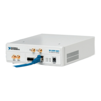
Figure 11. NI USRP-2930 Back Panel
GPS ANT is the input terminal for the GPS antenna signal. GPS ANT is an SMA (f) connector
with an impedance of 50
Ω.
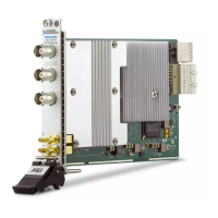
NI USRP-2932
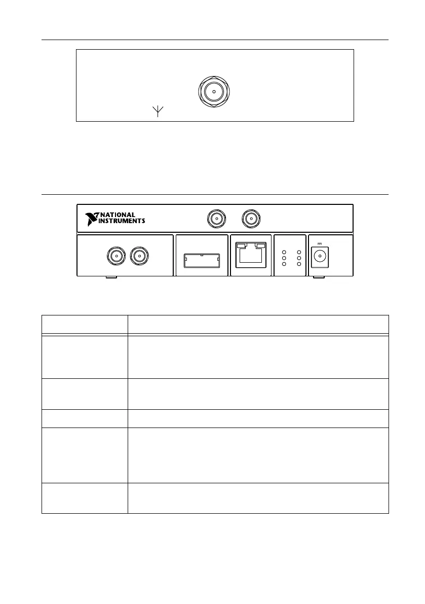
Figure 12. NI USRP-2932 Front Panel
MIMO EXPANSION GB ETHERNET
RX 1
TX 1
REF IN PPS IN
A
C
E
B
D
F
NI USRP
-
2932
40
0 MHz - 4.4 GHz
RX 2
POWER
6 V 3 A
Table 14. NI USRP-2932 Module Front Panel Connectors
Connector Use
RX1
TX1
Input and output terminal for the RF signal. RX1 TX1 is an SMA (f)
connector with an impedance of 50
Ω and is a single-ended input or
output channel.
RX2 Input terminal for the RF signal. RX2 is an SMA (f) connector with
an impedance of 50 Ω and is a single-ended input channel.
REF IN This terminal is not used for this device.
PPS IN Input terminal for the PPS timing reference. PPS IN is an SMA (f)
connector with an impedance of 50 Ω and is a single-ended input
channel. PPS IN accepts 0 V to 3.3 V TTL and 0 V to 5 V TTL
signals.
MIMO EXPANSION The MIMO EXPANSION interface port connects two USRP devices
using a compatible MIMO cable.
30
| ni.com | NI USRP-29xx Getting Started Guide
 Loading...