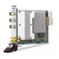
Table 16. NI USRP-2940R Module Front Panel Connectors (Continued)
Connector Use
RF 1 TX1 RX1 Input and output terminal for the RF signal. TX1 RX1 is an SMA (f)
connector with an impedance of 50
Ω and is a single-ended input or output
channel.
RX2 Input terminal for the RF signal. RX2 is an SMA (f) connector with an
impedance of 50 Ω and is a single-ended input channel.
Note The LED indications described in the following table occur only when you
use the NI-USRP
API with the default FPGA image. When you use LabVIEW
FPGA, you customize the LED indications.
Table 17. NI USRP-2940R Module LEDs
LED Indication
RF 0 TX1/
RX1
Indicates the transmit status of the module:
OFF—The module is not active.
RED—The module is receiving data.
GREEN—The module is transmitting data.
RX2 Indicates the receive status of the module:
OFF—The module is not receiving.
GREEN—The modules is receiving.
REF Indicates the status of the reference signal:
OFF—There is no reference signal or the device is not locked to the
reference signal.
BLINKING—The device is not locked to the reference signal.
GREEN—The device is locked to the reference signal.
PPS Indicates the pulse per second (PPS):
OFF—There is no reference signal or the device is not locked to the
reference signal.
BLINKING—The device is not locked to the reference signal.
GREEN—The device is locked to the reference time signal.
GPS Indicates whether the GPSDO is locked:
OFF—There is no GPSDO or the GPSDO is not locked.
GREEN—The GPSDO is locked.
NI USRP-29xx Getting Started Guide
| © National Instruments | 33
 Loading...