Table 26. NI USRP-2950R Module LEDs (Continued)
LED Indication
GPS Indicates whether the GPSDO is locked:
OFF—There is no GPSDO or the GPSDO is not locked.
GREEN—The GPSDO is locked.
LINK Indicates the status of the link to a host computer:
OFF—There is no link to a host computer.
GREEN/YELLOW/RED—The host is actively communicating with
the device.
RF 1 TX1/
RX1
Indicates the transmit status of the module:
OFF—The module is not active.
RED—The module is receiving data.
GREEN—The module is transmitting data.
RX2 Indicates the receive status of the module:
OFF—The module is not receiving.
GREEN—The modules is receiving.
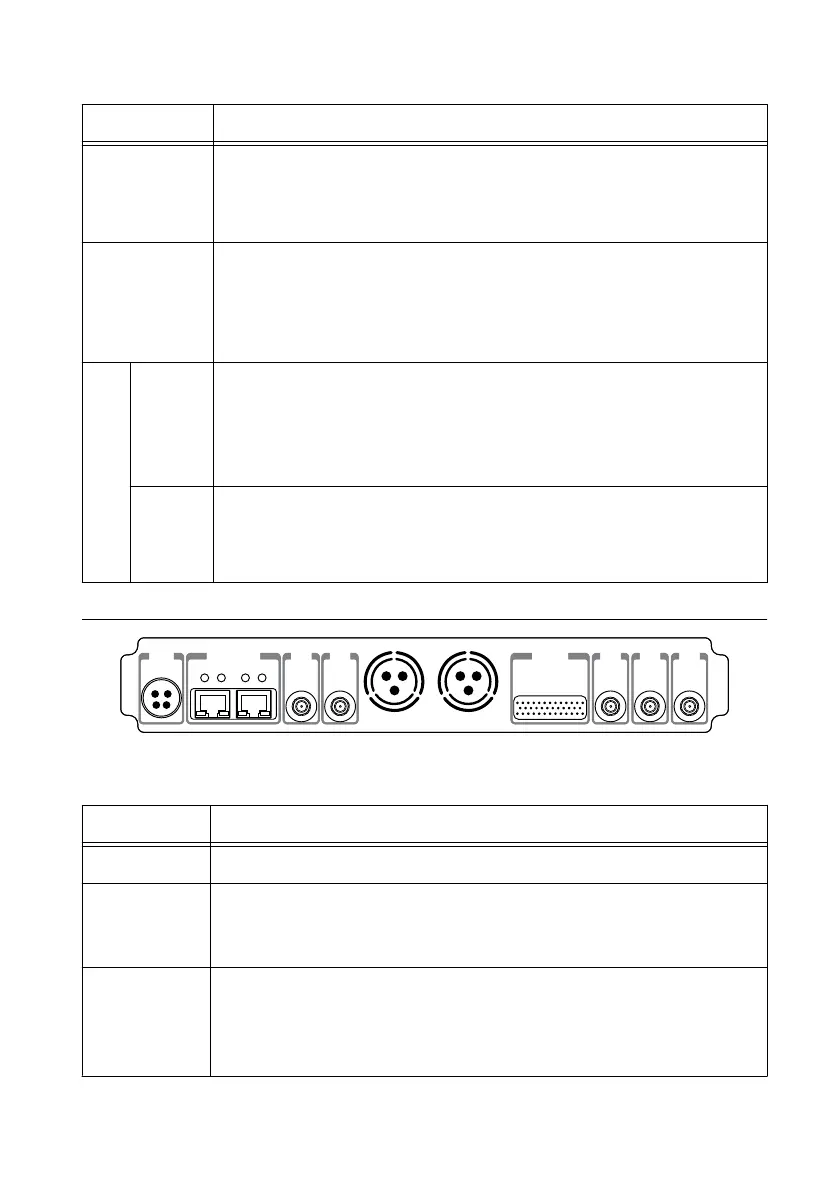
Figure 21. NI USRP-2950R Module Back Panel
0 1
PWR
REF
IN
PPS
OUT
TRIG
5V DC
REF
OUT
1G/10G ETH
3.3 V +15 dBm
MAX
9-16V DC
7
.5 A MAX
SFP+Ports
PCIe x4
TRIG
3.3V
IN
5V MAX
PPS GPS
ANT
–15 dBm
MAX
Table 27. NI USRP-2950R Module Back Panel Connectors
Connector Use
PWR The power input accepts a 9 V to 16 V, 6 A external DC power connector.
1G/10G ETH The Ethernet ports accept 1G SFP modules and 10G SFP+ modules. With
a 1G ETH module inserted, the ports accept gigabit Ethernet-compatible
cables (Category 5, Category 5e, or Category 6).
REF OUT Output terminal for an external reference signal for the LO on the device.
REF OUT is an SMA (f) connector with an impedance of 50
Ω and is a
single-ended reference output. REF OUT outputs a 10 MHz signal at
3.3 V.
44
| ni.com | NI USRP-29xx Getting Started Guide
 Loading...