59
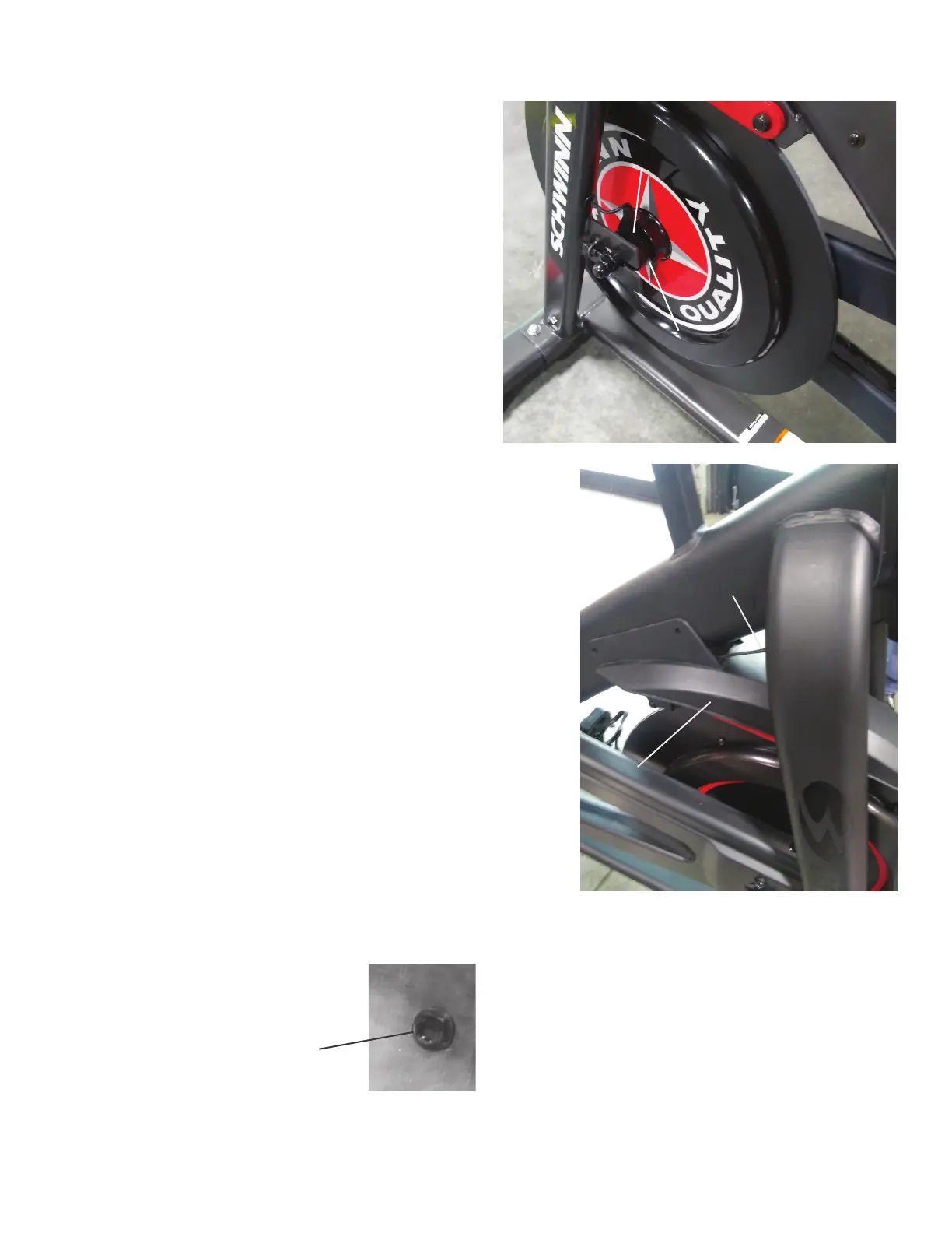
Speed Sensor
Speed Sensor
Magnet
25. Re-install all remaining parts that were removed in reverse order.
NOTICE: Do not crimp any cables. Install the Flywheel Tensioners
at the position that you recorded in step 15. Make sure
the Flywheel can turn easily. Verify that the Speed
Sensor and Speed Sensor Magnet on the Flywheel do
not touch.
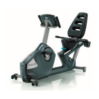
Re-install the Fender, making sure the Resistance Cable is routed
between the Frame and the top of the Fender.
Installation does not require the use of the Crank Puller. Be sure the
Crank Arms are connected at 180° from each other.
26. Make sure that the Drive Belt tension is correct. Refer to the “Adjust
the Belt Tension” procedure.
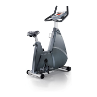
27. Add Loctite
®
272 (or equivalent) to the inner threads of the Crank
Nut. Do not to apply the Loctite
®
272 to the Crank Shaft.
Resistance Cable
Fender
Crank Nut