10
2. Push the cleat down and forward to engage the Pedal.
3. Repeat for the other foot.
4. Practice engaging and disengaging from the Pedals before starting your workout.
To disengage (release) the cleats from the pedals, push the heels outward and lift.
,IWKHERG\ZHLJKWRIDXVHULVYHU\ORZWKHXVHUPD\KDYHGLႈFXOW\ZLWKRSHUDWLRQRIWKH
engagement/release mechanism in the Pedals. It may be necessary to decrease the
retention force of the mechanism. To adjust the retention:
1. Locate the opening in the rear of the Pedal for access to the adjustment bolt. It is be-
tween the 2 screws that attach the Foot Restraint to the Pedal.
2. Use a 3mm hex wrench to turn the adjustment bolt. To decrease the retention, turn it left
(counterclockwise). To increase the retention, turn it right (clockwise).
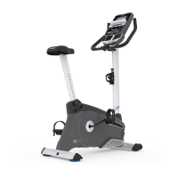
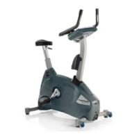
Handlebar Adjustment
To adjust the handlebar position:
1. Loosen the Handlebar Post Adjustment Handle on the Handlebar Post as you hold the
upright post to prevent it from dropping. Adjust the Handlebar to the desired height.
'RQRWOLIWWKH+DQGOHEDU3RVWDERYHWKH³6723´PDUNRQWKH+DQGOHEDU3RVW
2. Tighten the Handlebar Post Adjustment Handle to secure the Handlebar. Be sure that the
handle is fully tightened. Pull the handle out and turn so that it points down, then release.
NOTICE: Do not crimp the cables.
3. To move the Handlebar closer to, or away from the seat, loosen the Handlebar Slider
Adjustment Handle. Slide the Handlebar to the desired position and tighten the Handlebar
Post Adjustment Handle to secure the Handlebar. Be sure that the handle is fully tightened.
Pull the handle out and turn so that it points forward, then release.
1RWH If the handle cannot turn due to contact with another part, pull the handle, turn and push it
back in to reposition it. Continue turning as needed.
/RFNLQJWKH)O\ZKHHOIRU6WRUDJH
When the machine is not in use, be sure to lock the Flywheel with the Emergency Brake/Resistance Adjustment Knob.
To lock the Flywheel, turn the Emergency Brake/Resistance Adjustment Knob clockwise until it encounters an increase in
resistance. Then rotate the Emergency Brake/Resistance Adjustment Knob another 1/2 turn clockwise. The Flywheel is
QRZORFNHG7KHÀ\ZKHHOVKRXOGEHORFNHGIRUVWRUDJHRIWKHPDFKLQH
)RUVDIHVWRUDJHRIWKHPDFKLQHUHPRYHWKHSRZHUVXSSO\DQGSODFHLQDVHFXUHORFDWLRQ7LJKWHQWKH
%UDNH5HVLVWDQFH$GMXVWPHQW.QREDVGHVFULEHGXQWLOWKH)O\ZKHHOLVORFNHG3ODFHWKHPDFKLQHLQDVHFXUH
ORFDWLRQDZD\IURPFKLOGUHQDQGSHWV
With the Flywheel locked, the level of resistance will be out of the range of operation displayed by the Console. Do not
use the machine with the level of resistance outside of the 0% - 100% range. This will damage the ability to quickly stop
the Flywheel during an emergency, and the effectiveness of securing the bike for storage. Turn the Emergency Brake/
Resistance Adjustment Knob until the LEVEL displayed on the Console is less than 100%. The resistance is now in the
designed range of operation for the bike.
-
+
 Loading...