12
WM-4 Marine Weather & Audio Receiver Installation Manual
ANTENNAAUDIO
MARINE
NETWORK
RECEIVER
POWER
POWER
InfoLINK
• Each unit should have its own dedicated
power cable wired back to the distribution
panel.
Total Length
(max)
Supply
Voltage
Cable Gauge
(AWG)
0–5 m
(0–16.4 ft)
12 V 18
24V 20
5–10 m
(16.4–32.8 ft)
12 V 14
24V 18
10–15 m
(32.8–49.2 ft)
12 V 12
24V 16
15–20 m
(49.2–65.5 ft)
12 V 12
24V 14
Note: These distances are for a 2–wire power cable
run from the battery to the product (approximate
distance). To calculate the round trip length, double
the figure stated here.
Breakers, Fuses and Circuit Protection
It is recommended that you fit a thermal breaker or
fuse at the distribution panel.
• Thermal breaker rating: 5 A (if only connecting
one device)
Note: The suitable fuse rating for the thermal
breaker is dependent on the number of devices you
are connecting. If in doubt consult an authorized
Lowrance, Simrad, or B&G dealer.
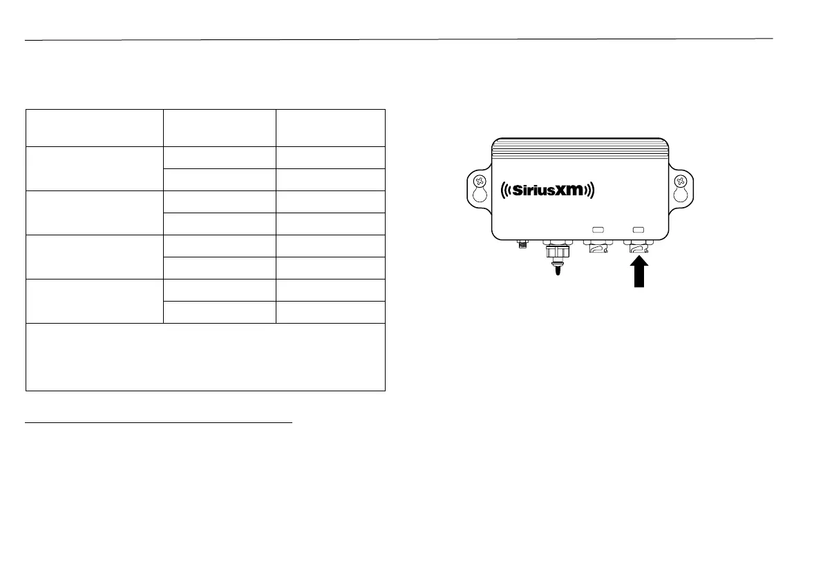
Connect the Power Cable to the POWER connection
of the receiver.
 Loading...