4. System Details
4.1 Setting the DIP Switches
CAUTION
Do not remove the front cover unless the power to the
boiler is turned off or disconnected.
Failure to do so
may result in electric shock.
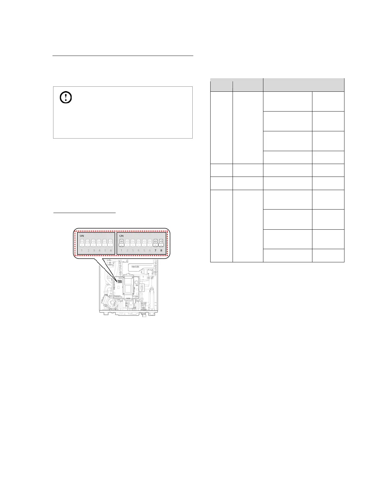
The boiler has two DIP switch locations: on the main circuit
board (PCB) and on the front panel. Each location has two sets
of DIP switches that control the functionality of the boiler. Set
the DIP switches appropriately, based on the installation
environment and the gas type.
4.1.1 Setting the DIP Switches
Circuit Board DIP Switches
Set of DIP Switches 1 (Set of 6)
The DIP switches 1 on the circuit board configure the boiler’s
model and gas type settings. These configurations are set at
the factory and should not be changed. The following tables
describe the functions of the DIP switches and their settings.
1 & 2
Operation
Mode
Normal
OFF
stage)
OFF
stage)
ON
5 & 6
Capacity
select
NCB-180
OFF
NCB-210
OFF
NCB-240
ON
 Loading...