c.
Fully open several hot water fixtures and set the boiler
to operate at 1-stage MIN mode (refer to “setting the
DIP Switches” on page 19 and Operation Condition
Setting on page 54).
Measure the CO
2
value at low fire.
If the CO
2
value is not within 0.5% of the value listed in
Table 2, the gas valve set screw will need to be
adjusted.
If adjustment is necessary, locate the set screw as
shown in Figure 8. Using a 5/32” or 4mm Allen wrench,
turn the set screw no more than 1/4 turn clockwise to
raise or counterclockwise to lower the CO
2
value.
Figure 8. Set Screw Location
NOTE
The set screw is located behind the screw-on cover. This
d.
Fully open several hot water fixtures and set the boiler
to operate at 2-stage MAX mode (refer to page 19 and
page 54). Measure the CO
2
value at high fire.
If the CO
2
values do not match Table 2 at high fire, do
not adjust the gas valve. Check for the proper Gas
Orifice in Table 3.
DANGER
Improper gas valve settings can cause severe personal
injury, death or substantial property damage.
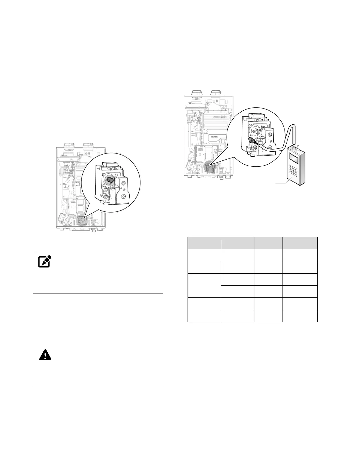
Option 2. Using Digital Manometer
a.
Open the offset pressure port by loosening the screw
two turns as shown in Figure 9.
Figure 9. Checking offset Gas Pressure with Manometer
b.
Connect a manometer to the offset pressure port. For
dual port manometers, use the positive pressure side.
NCB-180
NCB-210
NCB-240
Table 3. Offset values for low fire
Digital pressure
manometer
 Loading...