©Navien America Inc. 2010 NR/NP series service Manual
150
Version 2.0
8.2.13. Flow Sensor
1. Turn off the gas supply.
2. Turn off the 120V power supply.
3. Turn off the water supply. Drain all water
from the appliance.
4. Loosen the PCB 2 screw from bottom base.
5. Pull out the PCB. (refer to 8.2.1 PCB)
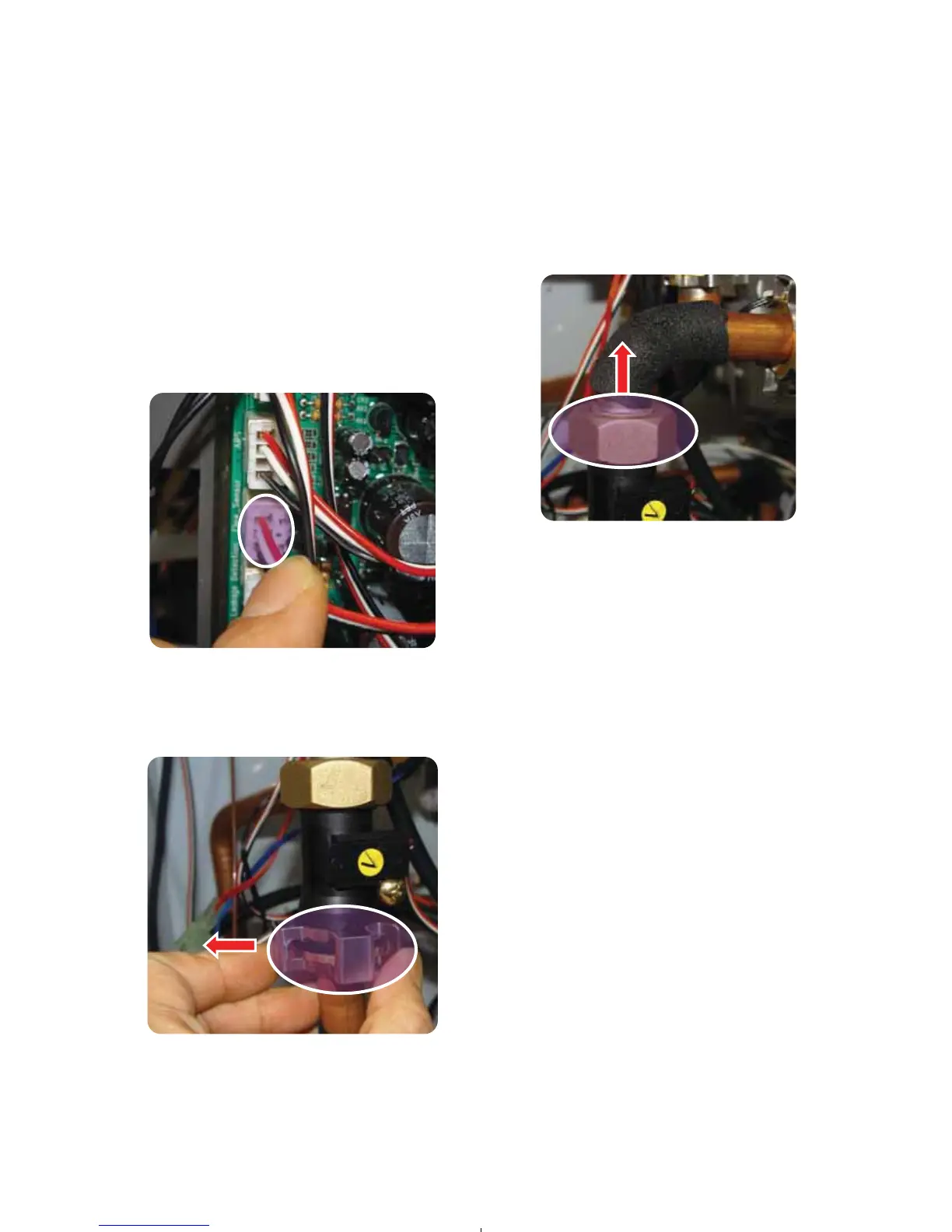
6. Remove the 2 stainless clips. (fastener “D”)
7. Pull out the flow sensor.
8. Replace with new flow sensor.
9. Connect the flow sensor wire housing into
the PCB.
10. Reseat the flow sensor into the cold water
inlet pipe and reattach the stainless clip.
11. Reseat the non-threaded of flow sen-sor
into the copper fitting.
12. Install front panel using 4(four) screws.
13. Turn on water supply, power supply, and
gas supply.
14. Open a hot water tap and ensure there are
no leaks at the water heater.
5. Remove the stainless clip at the bottom of
the flow sensor.
6. Removing the brass (stainless) nut from the
flow sensor.
< Figure 35 >
< Figure 34 >
< Figure 36 >
 Loading...