5
6
7
8
DANGER
●
When conversion is required, be sure to set the Front
Panel DIP switches according to the supply gas type.
●
Failure to properly set the DIP switches could cause
carbon monoxide poisoning, resulting in severe personal
injury or death.
11. Measure and adjust the gas/air ratio.
Option 1. Using Combustion Analyzer (recommended)
a. Loosen the screw, rotate the plate and remove the
gasket to access the emissions monitoring port as
shown in Figure 7.
b. Insert the analyzer into the port (Figure 7).
Figure 7
Figure 8. Set Screw Location
Note
The set screw is located behind the screw-on
cover. This must be removed rst.
d. Fully open several hot water xtures and set the water
heater to operate at 2-stage MAX mode (refer to
page 8). Measure the CO
2
value at high re.
If the CO
2
values do not match Table 2 at high re, do
not adjust the gas valve. Check for the proper Gas
Orice.
DANGER
Improper gas valve settings can cause severe personal
injury, death or substantial property damage.
b. Connect a manometer to the oset pressure port. For
dual port manometers, use the positive pressure side.
Model Kit Part No. Gas Type Oset
NPE-150S
NAC-N6 LP -0.03 in ± 0.01 in
NAC-L6 NG -0.04 in ± 0.01 in
NPE-180A
NPE-180S
NAC-01 LP -0.03 in ± 0.01 in
NAC-100 NG -0.04 in ± 0.01 in
NPE-210A
NPE-210S
NAC-02 LP -0.02 in ± 0.01 in
NAC-200 NG -0.04 in ± 0.01 in
NPE-240A
NPE-240S
NAC-03 LP -0.02 in ± 0.01 in
NAC-300 NG -0.04 in ± 0.01 in
Table 3. Oset value for low re
c. Fully open a hot water xture and set the water heater
to operate at 1-stage MIN mode (refer to page 8).
Measure the oset value at low re and compare it to
the values in Table 3. If the oset value is out of range,
the gas valve set screw will need to be adjusted.
If adjustment is necessary, locate the set screw as
shown in Figure 10. Using a
5
/
32
in or 4 mm Allen
wrench, turn the set screw no more than
1
/
4
turn
clockwise to raise or counterclockwise to lower the
oset value.
12. Once the CO
2
or oset values have been conrmed,
apply the included conversion stickers to show that the
appliance has been converted to propane gas. Place this
labels adjacent to the rating plate as shown in Figure 11.
Orice Size / Injecteur:
Min. 4.5 mm to Max. 4.8 mm
This unit has been
converted to Propane fuel
Cet appareil a ete converti au Propane
Manifold Gas Pressure /
Pression à la tubulure d’alimentation:
Min. -0.02 to Max. -0.66 inches WC
BTU Input / Debit calorique:
Max. 180,000 - Min. 19,900 BTUh
Conversion Kit No.: NAC-02
Inlet Gas Pressure / Pression d'entrée du gaz:
Min. 8.0 to Max. 13.0 inches
with Kit No. ________________________
This water heater was converted on
(name and address of organization making
this conversion, who accepts responsibility
for the correctness of this conversion)
______/______/______ to ____________ gas
by _________________________________
_________________________________
Figure 11. Proper Placement of Gas Conversion Labels
Note
Manifold Gas Pressure ratings can change due
to updated orice sizes. Please conrm new
manifold pressures approved by CSA before
production of gas conversion labels.
Water
Heater
Fuel
High re Low re
%CO
2
%CO
2
NPE-150S
NG 8.9 9.5
LP 10.2 10.8
NPE-180A
NPE-180S
NG 8.9 9.5
LP 10.2 10.8
NPE-210A
NPE-210S
NG 8.9 9.5
LP 10.2 10.8
NPE-240A
NPE-240S
NG 8.9 9.5
LP 10.2 10.8
Table 2. CO
2
and CO value
(CO
2
values must be within 0.5% of the values listed.)
c. Fully open several hot water xtures and set the water
heater to operate at 1-stage MIN mode (refer to page 8).
Measure the CO
2
value at low re.
If the CO
2
value is not within 0.5% of the value listed
in Table 2, the gas valve set screw will need to be
adjusted.
If adjustment is necessary, locate the set screw as
shown in Figure 8. Using a
5
/
32
in or 4 mm Allen wrench,
turn the set screw no more than
1
/
4
turn clockwise to
raise or counterclockwise to lower the CO
2
value.
Option 2. Using Digital Manometer
a. Open the oset pressure port by loosening the screw
two turns as shown in Figure 9.
Figure 9
Figure 10
Note
The set screw is located behind the screw-on
cover. This must be removed rst.
d. At high re, do not check the oset value and never
adjust the gas valve.
DANGER
Improper gas valve settings can cause severe personal
injury, death or substantial property damage.
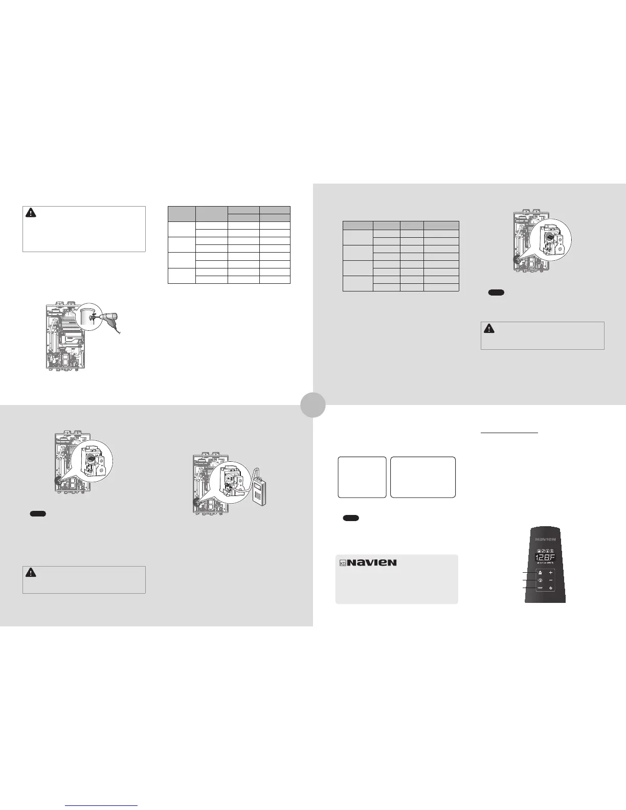
Setting the Operation Mode
1. Using the Front Panel, press and hold the Diagnostics
Button for over 5 seconds until “1.TST” is displayed.
2. Press the + (Up) button once to change the display to
“2.OPR”.
3. Press the Information Button once to acess the Operation
Mode menu.
4. Press the + (Up) button once to set the water heater to
opearate at 1-stage MIN (“MIN.1”).
5. To set the water heater to operate at 2-stage MAX (1-stage
MAX for NPE-150S), press the + (Up) button 3 times or until
“MAX.2 (MAX.1 for NPE-150S)” is displayed.
6. To exit the Operation Mode and return the water heater to
normal operation, press the Reset button twice.
Diagnostics
Information
Reset
Navien, Inc.
20 Goodyear lrvine, CA 92618
TEL 1-800-519-8794 FAX 1-949-420-0430
www.navien.com
 Loading...