INSTALLATION/ SERVICE MANUAL
INSTALLATION/ SERVICE MANUAL
37
38
APPENDIX A
APPENDIX A cont’d
navitasvs.com/support
navitasvs.com/support
Navitas
AC Motor Controller
WVUR
B-
B+
1614
12108642
1513
1197531
3230282624
222018
31292725
23211917
34 3533
8 7 6 5
4 3 2 1
OTF
Using TAC2 Module PN: 40-000620
20201208 Original
Revision History
Fuse
Battery
Pack
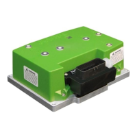
Wiring Diagram - EZGO RXV (After Jan 23, 2012)
8 POS Molex
39-01-3089 Housing
39-00-0040 Pin
1
Solenoid
P1: +12V POLY
P2: OTF REGEN
P3: OTF SPEED
P4: OTF ACCELERATION
P5: +5V EXT
P6: OTF LOOCK
P7: REVERSE BUZZER
P8: GND POLY
Key Switch & Direction
Speed Encoder
Reverse
Buzzer
GRN
BLK
8 7 6 5
4 3 2 1
P1: Key In / Logic Power In
P2: Reverse Buzzer
P3: na
P4: Brake Light Relay Release
P5: Brake Solenoid Out
P6: Main Solenoid Out
P7: Logic Power GND
P8: Motor Temperature In
P9: Foot Switch In
P10:Tow Switch In
P11:Charger Interlock In
P12:Brake Switch In
P13: na
P14: na
P15:+5V PF
P16:Throttle In
P17:Brake In
P18:Anolog GND
P19:na
P20:na
P21:na
P22:Forward In
P23:CAN Positive
P24:NA
P25:+12V Output
P26:+5V PF
P27:na
P28:na
P29:na
P30:SOC Display Out
P31:SPD A In
P32:SPD B In
P
33:Reverse In
P34:Analog Ground
P35:CAN Negative
1
35
Mating 35 POS
TE 776164-1
35 POS
TE 1-776231-1
OTF
On The Fly Programmer
16 14
12 10 8 6 4 2
15 13
11 9 7 5 3 1
32 30 28 26 24
22 20 18
31 29 27 25
23 21 19 17
3435 33
AC Motor
U
W
V
YEL
RED
WHT
L.BLU
YEL
ORG
PUR
Brake
Light
Relay
GRY
BLK
PUR
RED
Charger Interlock
(Close To Run)
Brake
Switch
WHT
BLU
Brake
Solenoid Coil
Forward
Reverse
Logic Power
Key
Pedal Box
RED
L.BLU
WHT
BLK
Brake
Resistor
Motor Temp
PNK
TOW
Switch
SOC Display
Brake Sensor
(Built in)
BLK
Bi-metal
Switch
L.GRN
RED
BLK
Connectors on
Navitas module 40-000620
BLK
+
-
Out
P1: RED
P2: BLK
P3: na
P4: PUR
P5: BLK
P6: BLK
P7: BLK
P8: PNK
P9: L.BLU
P10:BLK
P11:L.BLU
P12:WHT
P13: na
P14: na
P15:ORG
P16:YEL
P17:L.GRN
P18:BLK
P19:na
P20:RED
P21:na
P22:GRN
P23:RED/WHT
P24:na
P25:PUR
P26:ORG
P27:na
P28:YEL
P29:ORG
P30:GRY
P31:BLU/WHT
P32:WHT
P33:WHT
P34:GRN/WHT
P35:ORG/RED
1
Throttle
Foot Swith
+5V
SPDA
GND
SPDB
ORG
BLK
L.BLU
GRN/BLK
GND
CAN-N
CAN-P
BLK
ORG/RED
RED/WHT
CAN Port
Depending on year,
SOC+ could connect
to in stead of 12V.
1210
8642
119
7531
22201816
14
23211917
1513
8 7 6 5
4 3 2 1
OTF
Navitas
AC Motor Controller
WVUR
B-
B+
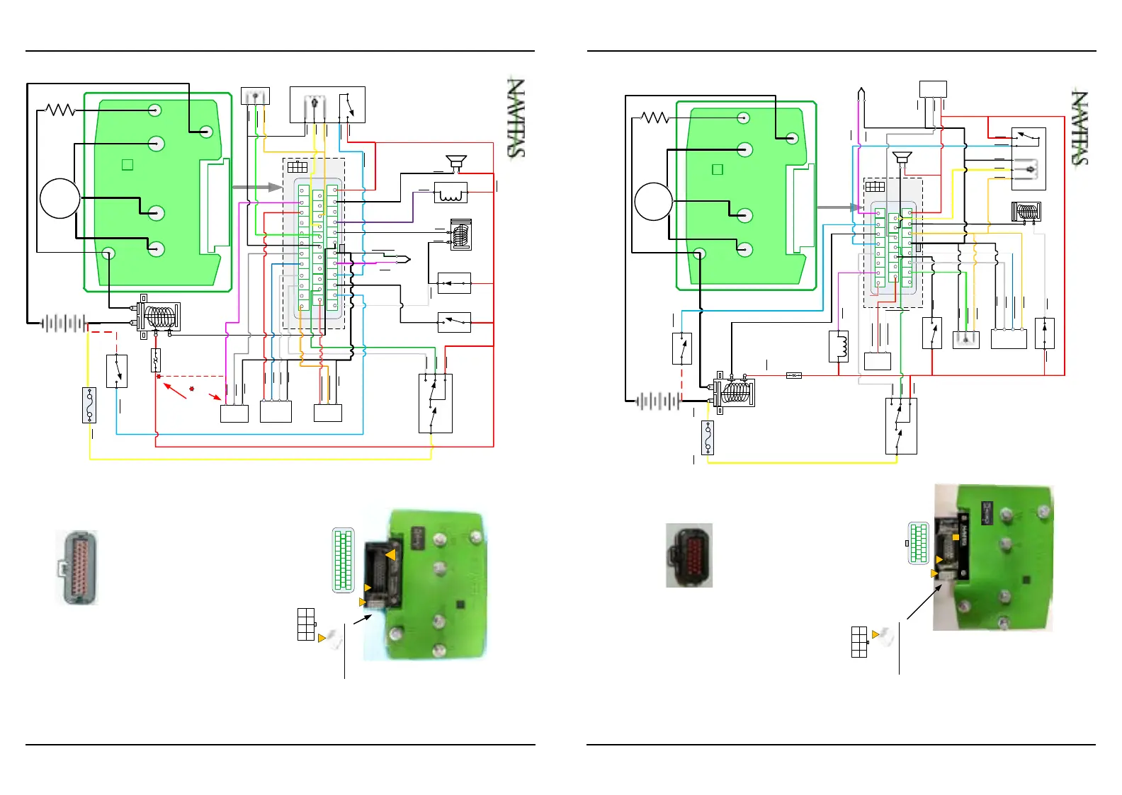
Using TAC2 Module PN: 40-000623
20210415 Original
Revision History
Fuse
Battery
Pack
Wiring Diagram - EZGO RXV Danaher ( Dec 2009-Jan 2012)
8 POS Molex
39-01-3089 Housing
39-00-0040 Pin
1
Solenoid
P1: +12V POLY
P2: OTF REGEN
P3: OTF SPEED
P4: OTF ACCELERATION
P5: +5V EXT
P6: OTF LOOCK
P7: REVERSE BUZZER
P8: GND POLY
Key Switch & Direction
Speed
Encoder
Reverse
Buzzer
GRN
8 7 6 5
4 3 2 1
Mating 23 POS
TE 770680-1
OTF
On The Fly Programmer
AC Motor
U
W
V
YEL
RED
WHT
BLU/WHT
ORG
RED
BLK
PUR
Brake Light Relay
GRY
BLK
RED
RED
Charger
Interlock
(Close To Run)
Brake Switch
BLK
RED
Brake Solenoid
Coil
Forward
Reverse
Logic Power
Key
Pedal Box
BLK
Brake
Resistor
Motor Temp
PNK
TOW Switch
SOC
Display
Brake
Sensor
(Built in)
BLK
Bi-metal
Switch
L.GRN
ORG
BLK
Connectors on
Navitas module 40-000623
+
-
Out
P1: Key In / Logic Power In
P2: Brake Solenoid Out
P3: +5V PF
P4: AGND
P5: SPD A In
P6: SPD B In
P7: Brake In
P8: CAN GND
P9: Throttle In
P10:Reverse Buzzer Out
P11:SOC Display Out
P12:Forward In
P13:Tow Switch In
P14:NA
P15: CAN NEG
P16:Motor Temperature In
P17:Charger Interlock In
P18:MAIN Solenoid Out
P19:Foot Switch In
P20:Reverse In
P21:Resistor Control (Not Used)
P22:Brake Light Relay Release
P23:CAN POS
23-POS Ampseal
776228-1
Module 40-000623
TAC2 for RXV Danaher
1
23
12 10
8 6 4 2
11 9
7 5 3 1
22 20 18 16
14
23 21 19 17
15 13
WHT
L.BLU
WHT
L.BLU
ORG
YEL
P1: RED
P2: BLK
P3: ORG
P4: BLK
P5: BLU/WHT
P6: WHT
P7: L.GRN
P8: BLK/WHT
P9: YEL
P10:BLK
P11:GRY
P12:GRN
P13:BLK
P14:GRY
P15:ORG/RED
P16:PNK
P17:L.BLU
P18:BLK
P19:L.BLU
P20:WHT
P21:PUR/WHT
P22:PUR
P23:RED/WHT
1
D:+5V
C:SPDA
A:GND
B:SPDB
A
B
C
ThrottleFoot Switch
A
B
C
YEL
GND
CAN-N
CAN-P
CAN Port
BLK/WHT
ORG/RED
RED/WHT
 Loading...

