INSTALLATION/ SERVICE MANUAL
INSTALLATION/ SERVICE MANUAL
9
10
INSTALLATION INSTRUCTIONS
ATTENTION:
• Before installing the controller make sure that the golf car’s electrical
system is working properly.
• All components such as the motor, Run/Tow switch, pedal cluster, FWD/
REV switch and all wiring needs to be in good condition and operating to
manufacturer’s standards.
• The batteries must be in good condition and each battery must hold a
charge!
• If the system is not working properly this must be repaired before installing
this controller!
FAILURE to follow the WARNINGS below can damage the
Vehicle and/or cause SERIOUS INJURY OR DEATH!
DANGER
Installation or Servicing of the NAVITAS 440A / 600A 36-72V Controller must be done by
a trained golf car technician. Before installing or servicing of the NAVITAS Controller:
• Disconnect the main (+) positive and (-) negative cable on the vehicle’s battery system.
• Make sure the Run/Tow switch is in the To w position (if vehicle has one)
• The Key is turned OFF and removed from the ignition
• The parking brake is engaged
• Before testing the controller/vehicle make sure ALL four wheels are o the ground and
supported with jack stands.
• The area around the vehicle must be clear. Keep all people, children and pets away
from the vehicle when installing, servicing or testing the vehicle.
• Read NAVITAS 440A / 600A 48-72V Controller Installation/Service and all warning
labels before servicing or troubleshooting this Vehicle.
• The controller is sealed and cannot be opened for service. To replace the controller
call your local dealer. Opening the controller will void the warranty
• Wear safety glasses and gloves when installing this controller.
• Wear a safety shield when working in or near the vehicle battery compartment.
• Use insulated tools to protect from electric burns.
• Never lay or put down tools in the vehicle battery compartment.
• Remove pre-charge resistor and diode (if present) from contactor and discard.
INSTALLATION INSTRUCTIONS
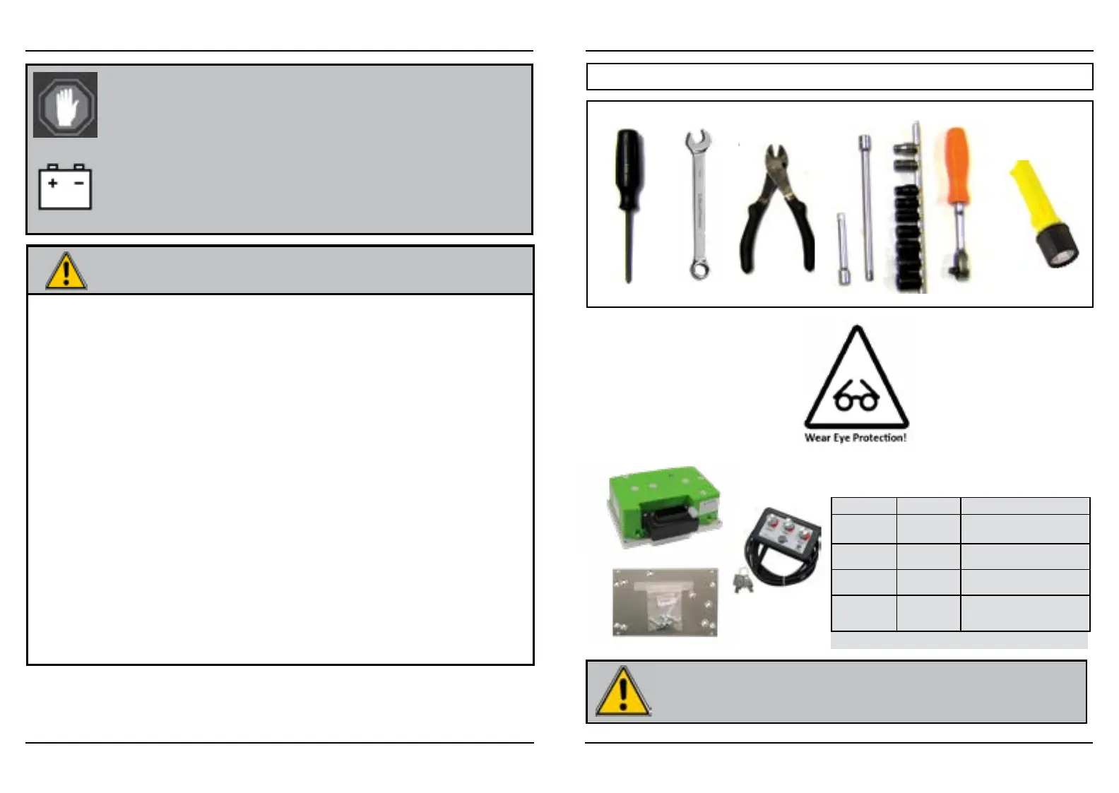
REQUIRED TOOLS
• #3 Phillips screwdriver
• 10, 11, & 13mm wrench
• Socket driver w/ extension
• Wire cutters
• Assorted socket set
• Safety glasses
• Flashlight (optional)
REQUIRED TOOLS & PARTS
Disconnect all batteries before beginning
installation. If the car has a Run/Tow switch, you
must place the switch in the TOW position first!
CAUTION
PURCHASED PARTS
• Controller w/ Bluetooth
• Mounting Plate w/ hardware
• On-The-Fly Programmer
Location Size Torque
Controller
Mounting
1/4x20 - RXV
M5x60
108 in-lbs/ 9 ft-lbs/12.3 Nm
Controller
Terminals
6 mm Bolt 88 in-lbs/ 7.5 ft-lbs/ 10 Nm
Motor
Mounting
84 in-lbs/ 7 ft-lbs/ 9.5 Nm
Wire
connections on
motor
144 in-lbs/ 12ft-lbs/ 16.2
Nm
Torque Specifications
 Loading...

