INSTALLATION/ SERVICE MANUAL
INSTALLATION/ SERVICE MANUAL
3
4
Speed Control
• To maximize your vehicle’s driving range only use the speed you need if using the OTF.
• Use the speed knob to control your maximum cruising speed, turn the speed down to the
minimum practical speed necessary for the application. The controller significantly increases
the operating eciency of the motor as the maximum speed adjustment is reduced.
• Minimize acceleration - hard acceleration demands high in-rush currents from the battery
pack. This increases wear and tear on both the motor and the mechanical systems.
Hill Descent
• Use regenerative braking for hill descent - it puts energy back into the battery and it increases
the life of your brakes. Regenerative Braking can be applied gradually and can reduce the
likelihood of losing traction when going down a hill.
• Limit the speed going downhill with fully charged lithium batteries to prevent issues with the
lithium BMS from shutting down or having the bleed o resistor over temp and engaging the
Motor Brake (E-Z-GO RXV)
Low Battery Warning
• When the battery discharged warning (3-1 flash) is given by the OTF (if present), the controller
will reduce the amount of power it supplies to the motor to protect the motor.
• Cycling the key will reset full controller power for 1 minute but doing so repeatedly will
adversely aect the life of your motor. Recharge the batteries as soon as possible.
Heavy Duty Usage
• If you notice that your cables or motor are becoming too hot to touch, then your application
is probably too demanding and we recommend that you upgrade the motor to a speed/torque
system, and upgrade the cables to at least 4 AWG, with 2 AWG being preferable and upgrade
the solenoid to 200A or bigger.
Warnings
• Always monitor the motor & battery wiring temperatures after changing the programmer
settings (if OTF is present) – particularly when going to higher speeds
• If your battery pack is full, the amount of regenerative braking may be reduced since the
controller has nowhere to put the excess energy.
Installation and Maintainance
• Torque the mounting bolts and the wire connections per the chart on page 10. Check torque of
the wire connections monthly to prevent them from loosening up, overheating and voiding the
warranty.
• Do not put flat or lock washers between the controller post and the wire. Washers go on top of
the wire and under the bolt head for best electrical connection.
• If the vehicle is going to in damp or wet conditions, add a small amount of dielectric grease to
the connections to help keep moisture out of the OEM connectors.
• Make sure the motor and wires are from rubbing by the frame and/or suspension. Rotate the
motor if needed to keep connections clear.
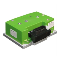
NAVITAS TAC 2 48-72V 440A / 600A Controller
AC INDUCTION MOTOR CONTROLLER
• The owner, and all vehicle operators MUST read and understand all warnings and instructions
in this manual and in the Vehicle Owner/Operator’s Manual. The owner of this vehicle assumes
all liability for accidents, injuries or damages if the warnings and instructions are not followed.
• Navitas Vehicle Systems Ltd. assumes no responsibility for errors or omissions in this manual,
in regards to liability or damages resulting from the use of information contained in the manual.
If it is lost or damaged please contact your local dealer.
• Navitas Vehicle Systems Ltd. reserves the right to make changes to the controller, parts of the
controller, accessories, labelling or instructions without obligation to make these changes on
units previously sold.
• Product and specifications are subject to change without notice or obligation.
ATTENTION:
• BEFORE INSTALLING THIS CONTROLLER PLEASE RECORD THE SERIAL NUMBER LOCATED ON THE
FRONT OF THE CONTROLLER AND WILL BE IN THE FORMAT OF 10-000XXX-XX.
INTRODUCTION
BEST PRACTICES
Controller Model # SERIAL #
 Loading...

