_______________________________________________________________________________________
_______________________________________________________________________________________
Page 14 of 16
7 Wiring diagram
Binder Plug Series 712-M9 IP67 (Colour coding acc. to DIN 47100)
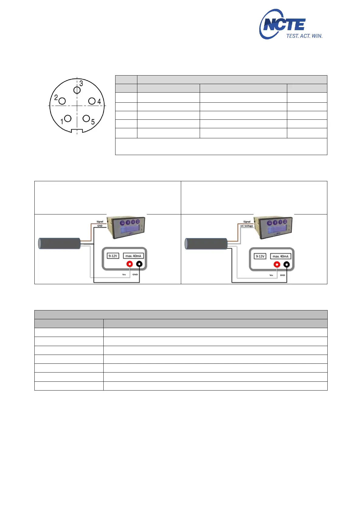
Connector
Power supply and outputs
The output V
ref
is a constant 2.5 V output and represents the virtual zero
point for direct +/- torque measurement.
8 Sensor wiring
Wiring for measurements
between 0.5 V … 4.5 V
approx. 2.50 V correspond to 0Nm
The grey and blue wires are not required.
Wiring for measurements
between -2.0 V … +2.0 V
approx. 0 V correspond to 0 Nm
The blue wire is not required.
9 Order options
Series 2100 (Square shaft)
including 5m cable and calibration certificate
including 5m cable and calibration certificate
including 5m cable and calibration certificate
including 5m cable and calibration certificate
including 5m cable and calibration certificate
including 5m cable and calibration certificate
including 5m cable and calibration certificate