L R M - 10 – U s e r M a n u a l
8
Operation
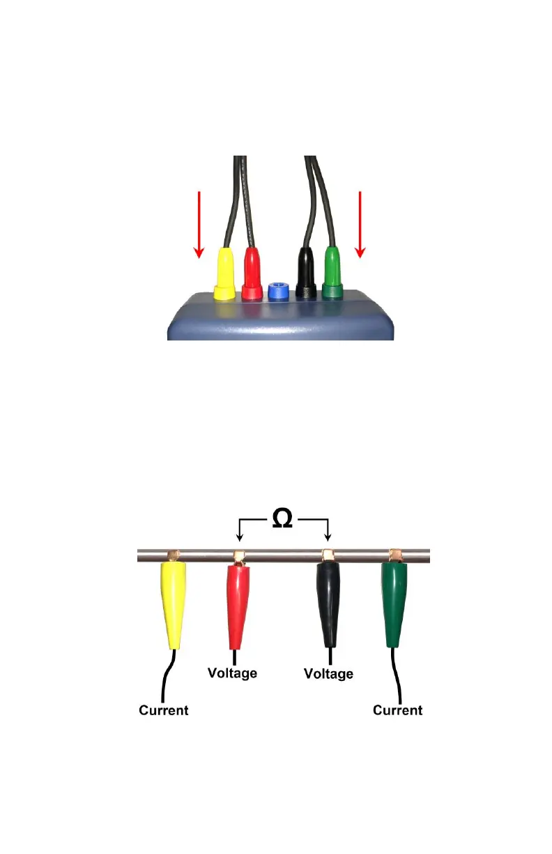
Connect the test leads to the LRM-10 micro-ohmmeter. Make sure to
connect each lead in the proper connector of the same color, on the
LRM-10 micro-ohmmeter.
The yellow and green clips are installed to both extremity of the device
under test. They allow a pulsed current to travel through the device
under test.
The red and black clips are installed between the two current injection
points (yellow and green). The instrument will measure the voltage
drop between the red and black clips. The instrument will then be able
to measure the resistance between the red and black clips. See figure
below: