English−23
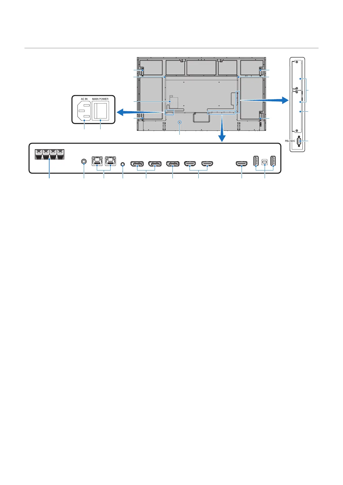
Terminal Panel
USB-A
DisplayPort
IN 1
DisplayPort
IN 2
DisplayPort
OUT
HDMI IN 1
(ARC)
HDMI IN 2 HDMI OUT
LAN 1LAN 2
EXTERNAL SPEAKER
AUDIO OUT
USB-B
SERVICE
REMOTE
IN
HDMI
3 4 5 6 7
#
&
@
8 9 0 !
$
$
$
*
*
$
^
%
1 2
1
AC IN Connector
Connects with the supplied power cord.
2
Main Power Switch
On/Off switch to turn main power ON/OFF.
3
EXTERNAL SPEAKER TERMINAL
Outputs the audio signal.
Red terminal is plus (+).
Black terminal is minus (–).
NOTE: Please contact your supplier for a list of compatible
Option Speakers.
4
AUDIO OUT
Audio signal output from DisplayPort and HDMI to an
external device (stereo receiver, amplier, etc.).
NOTE: This connector is not a headphone terminal.
5
LAN Port 1/2 (RJ-45)
Connect to LAN in order to manage and control the monitor
over the network.
Control multiple monitors when using a LAN daisy-chain
connection.
NOTE: • Please connect the LAN cable to the LAN1 port
for LAN network communications.
• Please refer to Multiple Monitors Connection
(see page 65).
6
REMOTE
Use an optional sensor unit by connecting it to your monitor.
NOTE: • Do not use this connector unless specied.
• When the optional sensor unit is connected, the
monitor’s remote control sensor is disabled.
7
DisplayPort IN 1/2
DisplayPort signals input.
8
DisplayPort OUT
DisplayPort signals output.
9
HDMI IN 1/2 (HDMI1 (ARC)/HDMI2)
HDMI signals input.
NOTE: • HDMI1 terminal also supports ARC (Audio
Return Channel) for audio output.
• ARC sends the monitor’s sound to audio
equipment with an HDMI1 ARC connector.
• Use the included ARC-supported HDMI cable.
The audio equipment will output the monitor’s
audio.
• The audio equipment can be controlled with the
included remote control.
0
HDMI OUT
HDMI signals output.
!
USB ports
For the USB port information, please see “Connecting a
USB Device” on page 34.
USB-A (Hub/0.5 A): Downstream port (USB Type-A).
USB-B (Ctrl): Upstream port (USB Type-B).
Service (2A): Service port. Power supply for USB devices.
Connect a color sensor MDSVSENSOR 3.
@
Option Board Slot
Slot for installation of an Intel
®
SDM.
NOTE: Please contact your supplier for a list of
compatible Option Boards.