ND-70373 (E) CHAPTER 2
Page 11
Revision 1.0
INSTALLATION PROCEDURE
4.1 Cable Connection
Connect CPR-related cables as shown in Figure 2-6 and Table 2-2.
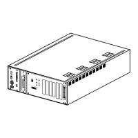
Figure 2-6 Cable Connections for IMGdxh
BUS1A BUS0A
PIM0PIM0 PIM0
HSWM BZ-C10
PZ-PW92
PZ-PW92
BASEUBASEU
HSWM
BASEU
HSWM
BASEU
PZ-M371
PA0
PB0
BUS0
BUS1
IOP1IOP0
IOP1IOP0 IOP1IOP0
PALM0
PALM
PALM1
PALM0
PWRB1
PWRB0
PWRA1
PWRA0
PZ-GT18PZ-GT18
CNA
CNB
CNA
CNB
PZ-GT17
PZ-GT19
CNA
CNB
CNA
CNB
PZ-GT17
PZ-GT19
IN
PWR
OUT
PWR
IN
PWR
OUT
PWR
CPR1
CPR0
BASEU
[13]
[1]
[7]
[2]
[3]
[4]
[5]
[6]
[9]
[8]
[10]
[11]
[12]
[14]
[16]
[16][15]
[7]
[15]
[8]
(Front View)
IMG3
(Front View)
IMG2
(Front View)
IMG1
(Front View)
IMG0
(Rear View)
IMG0
[1]~[8]: For system 0 [9]~[16]: For system 1
CN
CN
Note
Note
D
B
C
A
A
B
C
D
Note :
Connect these cables referring to the table below.
LPR Label on the Cable Corresponding GATE Card
CPR 0
CPU0. SLOT1/3 or CPU0. SLOT1/3/5B PZ-GT18 (CNB)
CPU0. SLOT2 or CPU0. SLOT2/5A PZ-GT18 (CNA)
CPU0. SLOT3 or CPU0. SLOT3/4 PZ-GT19
CPR 1
CPU1. SLOT1/3 or CPU1. SLOT1/3/5B PZ-GT18 (CNB)
CPU1. SLOT2 or CPU1. SLOT2/5A PZ-GT18 (CNA)
CPU1. SLOT3 or CPU1. SLOT3/4 PZ-GT19
 Loading...