Note:
The
n~imber
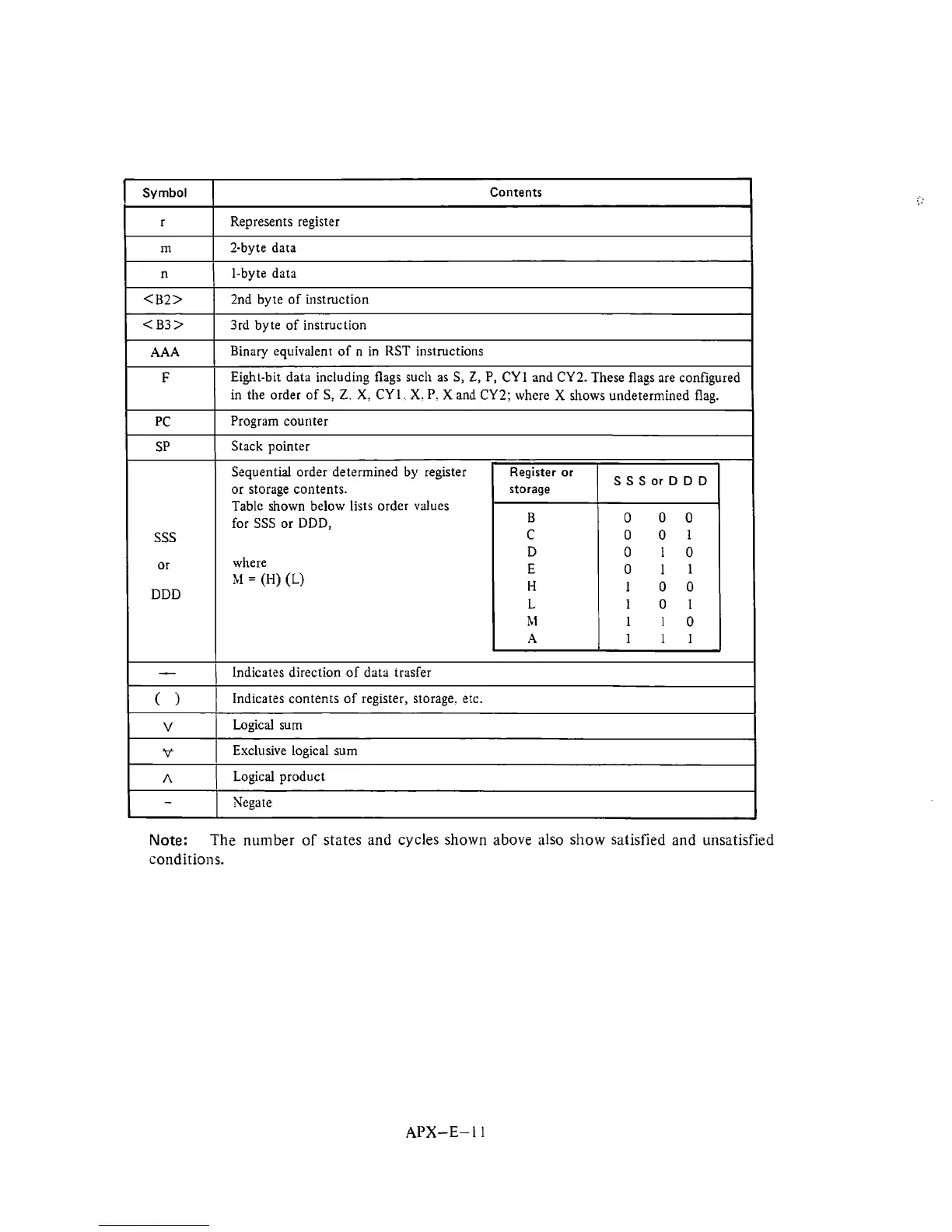
of states and cycles shown above also show satisfied and unsatisfied
conditions.
Symbol
r
m
n
<B2>
<B3>
AAA
F
PC
SP
SSS
or
DDD
-
(
1
V
%+
A
-
APX-E-
1
1
Contents
Represents register
?-byte data
1-byte data
2nd byte of instruction
3rd
byte of instruction
Binary equivalent of n in RST instructions
Eight-bit data including flags
such as S,
Z,
P,
CYl and CY2. These flags are configured
in
the order
of
S,
Z.
X,
CY1.
X.
P.
X
and
CY2; where
X
shows undetermined flag.
Program
counter
Stack pointer
Sequential order determined by register
or storage contents.
Table shown below
lists
order values
for SSS or DDD,
where
hi
=
(H) (L)
Indicates direction of data trasfer
Indicates contents of register, storage. erc.
Logical sum
Exclusive logical sum
Logical product
Negate
Register or
storage
B
C
D
E
H
L
M
A
SSSorDDD
0 00
0 01
0 10
0
11
100
101
110
111