5.3.2
S102 Port Operation
Test
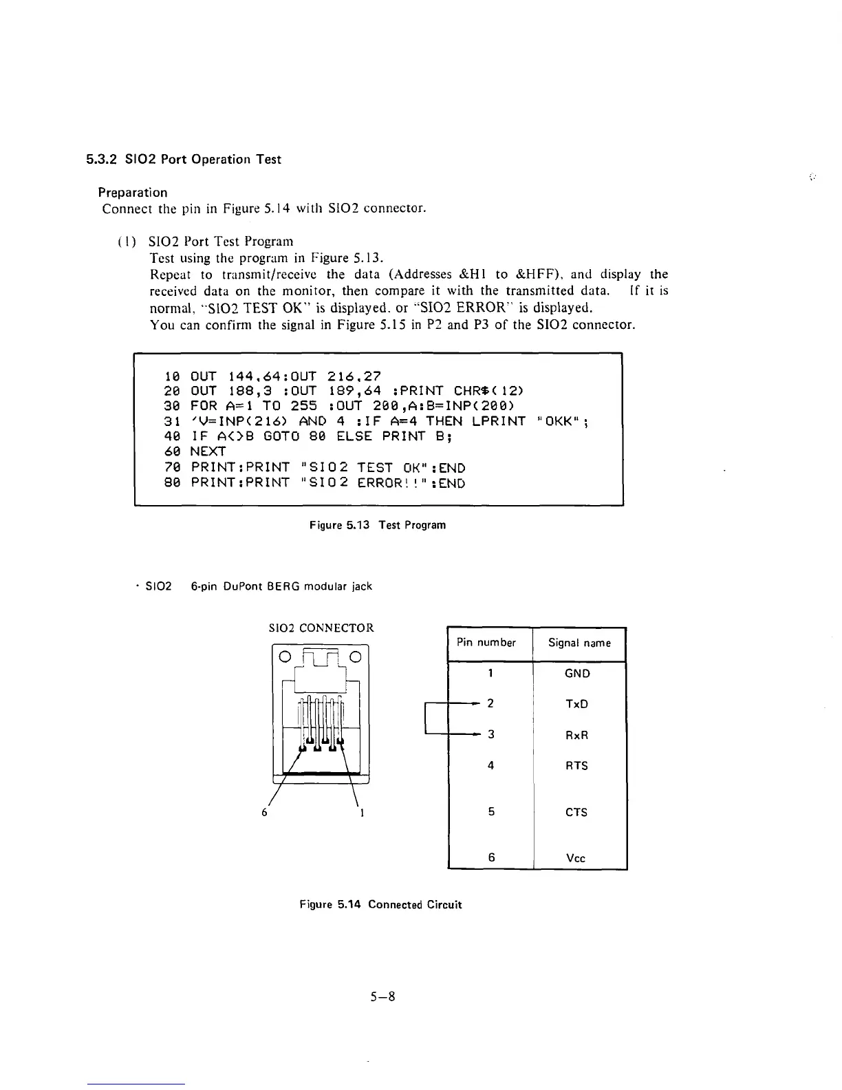
Preparation
Connect the
pin
in
Figure 5.14
with
902
connector.
(
I
)
SI02 Port Test Program
Test using the program in Figure 5.13.
Repeat to
transmitlreceive the data (Addresses
&M1
to SiHFF), and display the
received data on the monitor, then compare
it
with
the transmitted data.
If
it is
normal, 5102 TEST
OK"
is displayed.
or
"SI02
ERROR" is displayed.
You can confirm the signal in Figure 5.1
5
in
P2
and P3 of the S102 connector.
10 OUT 144.64:OUT 216.27
20
OUT 188,3 :OUT 189,64 :PRINT CHR%( 12)
30 FOR A=l TO
255
:OUT 260,A:B=INP(200)
31
'V=INP(216> AND 4
:IF
A=4 THEN LPRINT "OKK";
40 IF
A<>B
GOTO 80 ELSE PRINT
B;
60 NEXT
70
PR1NT:PRINT "SI02 TEST OKM:END
80 PR1NT:PRINT "SI02 ERROR!
!"
:END
-
Figure
5.13
Test Program
-
S102
6-pin DuPont BERG modular jack
S102
CONNECTOR
Figure
5.14
I
Connected Circuit
Pin number
1
--
2
-
3
4
5
6
Signal name
GND
TxD
RxR
RTS
CIS
Vcc