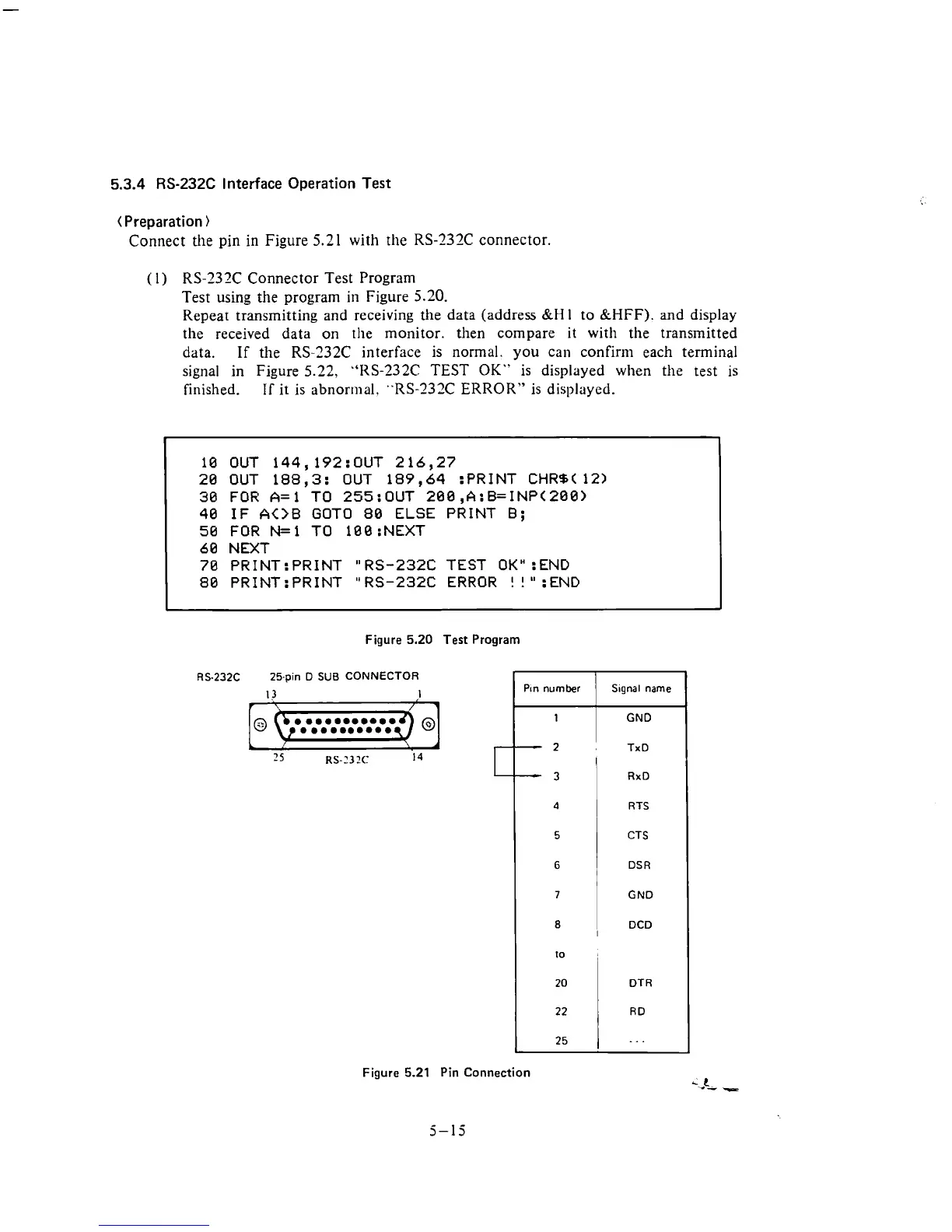
5.3.4
RS-232C
Interface Operation Test
(Preparation
)
Connect the pin
in
Figure
5.21
with the RS-232C connector.
(
1
)
RS-232C Connector Test Program
Test using the program in Figure 5.20.
Repeat transmitting and receiving
the
data (address
&H
1
to
&HFF).
and
display
the received data on
the monitor. then compare it with the transmitted
data.
If
the RS-232C interface is normal. you can confir111 each terminal
signal in Figure 5.22,
"RS-232C
TEST
OK"
is displayed when the test is
finished.
IT
it is abnormal, "RS-232C ERROR" is displayed.
10 OUT 144,192:OUT 216,27
20 OUT 188,3: OUT 189,64 :PRINT CHRB( 12)
30 FOR A=l TO 255:OUT 200,A:B=INP(200)
40 IF
A<>B
GOT0
80
ELSE PRINT
B;
50 FOR N=l TO 100 :NEXT
60 NEXT
70 PRINT: PRINT
"
RS-232C TEST
OK"
:END
80
PR1NT:PRINT "RS-232C ERROR
!
!":END
Figure
5.20
Test Program
RS.232C 25-pin D
SUB
CONNECTOR
Figure
5.21
Pin Connection
5-15
-
Pin
number
1
S~gnal name
GND
2
TxD
I
-
3
4
5
6
7
RxD
RTS
CTS
DSR
GND
1
DCD
10
I
20
22
25
DT
R
RD
. .
.