5.3.5
S101 Interface Operation
Test
(
Preparation
)
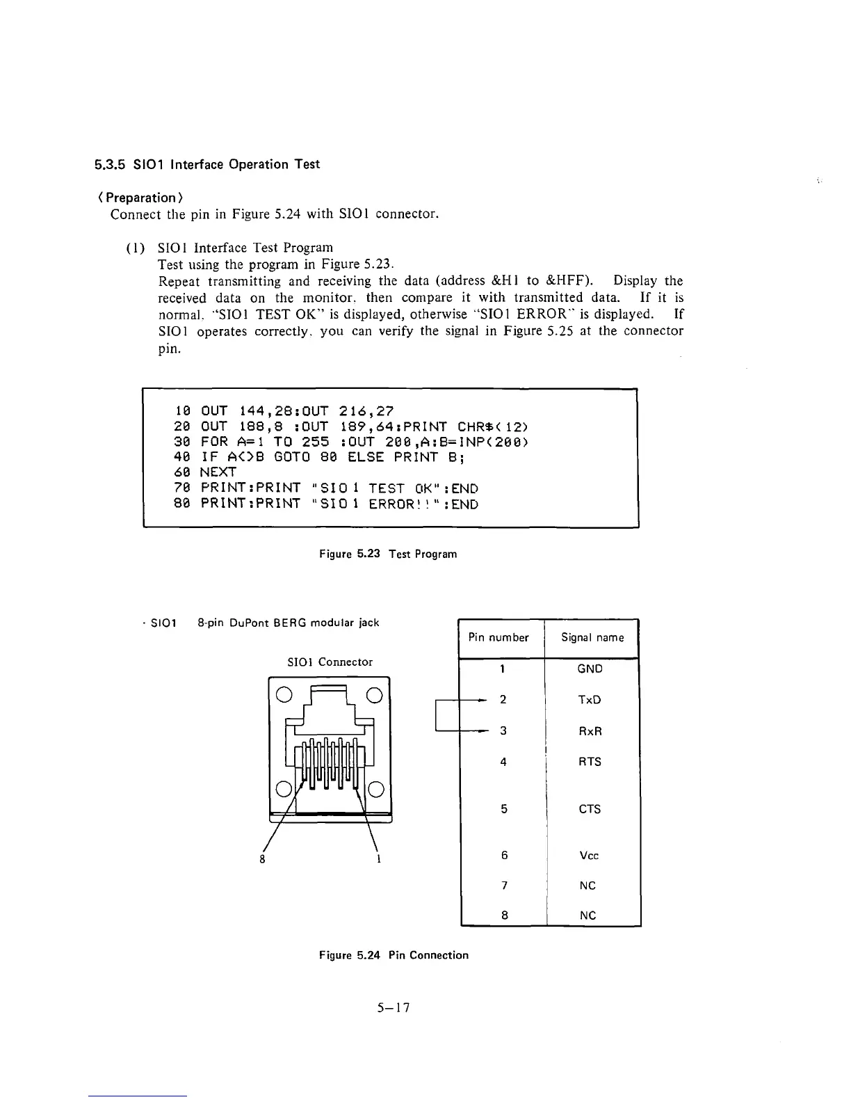
Connect the pin in Figure
5.24
with SlOl connector.
(
1) SIO
1
Interface Test Program
Test using the program
in
Figure
5.23.
Repeat transmitting and receiving the data (address
&Hi
to &HFF).
Display the
received data on the monitor. then compare it with transmitted data.
If
it
is
normal.
"ST01
TEST OIC" is displayed, otherwise "SIOl ERROR" is displayed.
If
SIOl operates correctly. you can verify the signal in Figure
5.25
at the connector
pin.
10 OUT 144,28:OUT 216,27
20 OUT 188,8 :OUT 189,64:PRINT
CHR%(
12)
30 FOR
A=l
TO 255 :OUT 200,A:B=INP(288)
40
IF
A<>B
GOT0 80 ELSE PRINT B;
60 NEXT
70
PR1NT:PRINT "SIO
1
TEST
OK"
:END
80
PR1NT:PRINT "SIO 1
ERROR!
!
"
:END
*
Figure
5.23
Test Program
-
SlOl
8-pin DuPont
BERG
modular jack
SIOl
Connector
Figure
5.24
Pin Connection
5-17
Pin
number
1
-
2
-
3
4
5
6
7
8
Signal
name
GND
TxD
RxR
!
R
TS
CTS
Vcc
N
C
N
C