(8)
OUT
D8
Operation Test
(
Preparation
)
Connect the pin 2
of
the RS-232C connector with the pin
3.
(See Figure 5.21
"Pin Connection" of item "RS-232C Interface Operating Test".
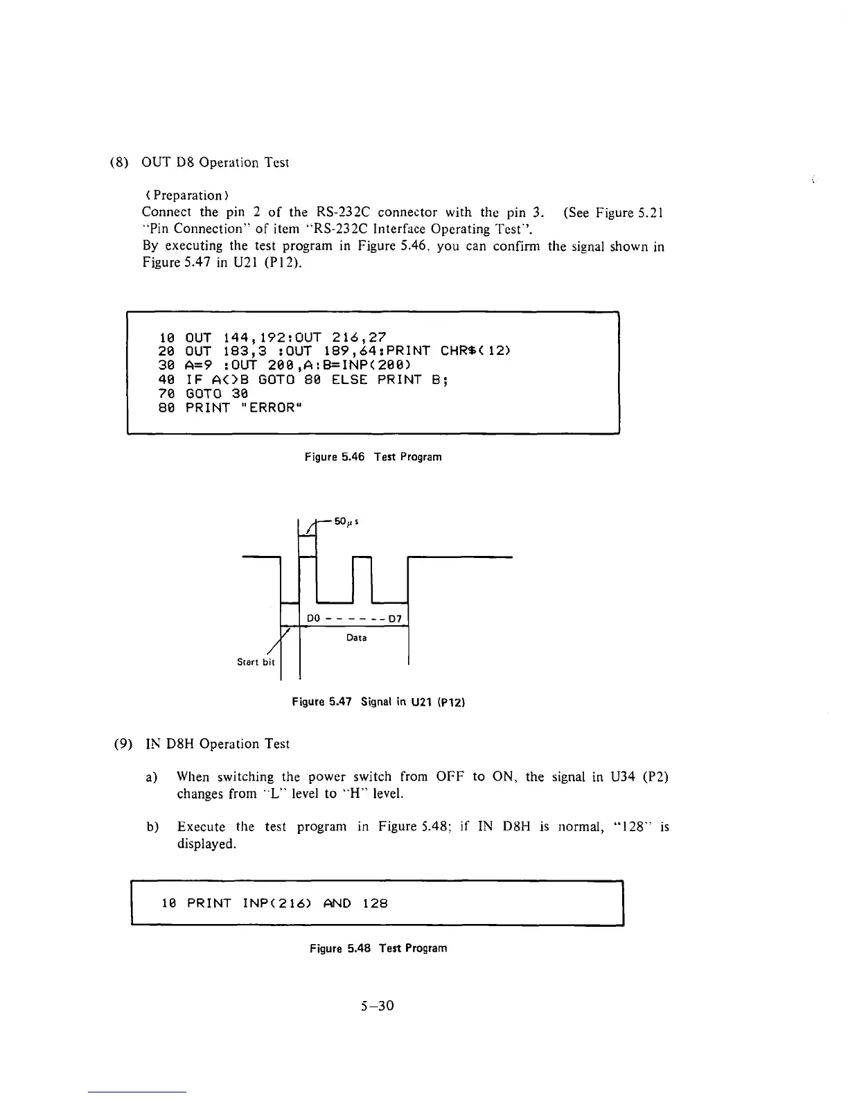
By
executing the test program in Figure 5.46. you can confirm the signal shown in
Figure
5.47 in U21 (P 12).
4
10 OUT 144,192:OUT 216,27
20 OUT 183,3 :OUT 189,64:PRINT CHRS(12)
30
A=9 :OUT
200
,A:B=INP(200)
40
IF AOB GOT0 80 ELSE PRINT
B;
70
GOT0
30
80 PRINT "ERROR"
Figure
5.46
Test
Program
Figure
5.47
Signal in
U21
(P12)
(9)
IN
D8H
Operation Test
a)
When switching the power switch from OFF to ON, the signal
in
U34
(P2)
changes from
"L"
level to
"H"
level.
b)
Execute the test program
in
Figure
5.48;
if
IN
D8H
is normal,
"128"
is
displayed.
10
PRINT INP(216) AND 128
Figure
5.48
Test Program
5-30