90 seconds
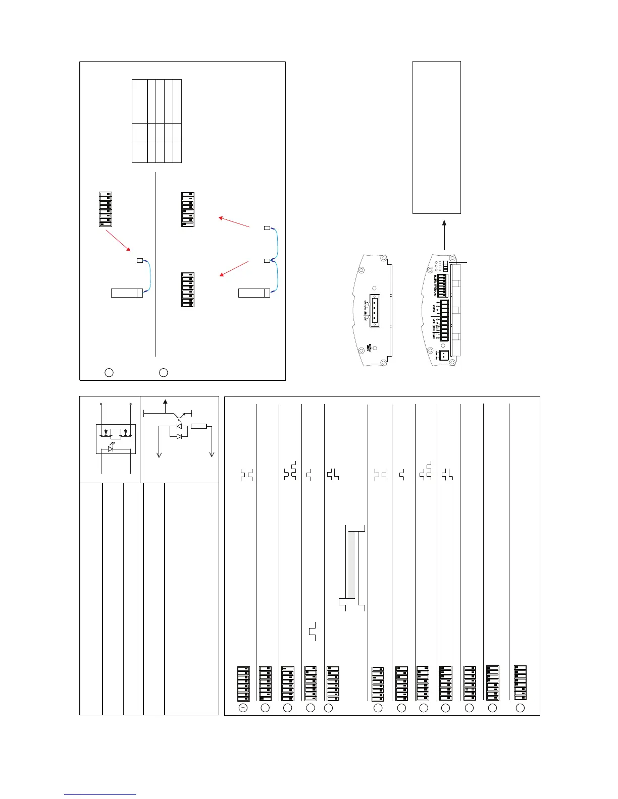
Program Switch settings (current version v6.8, version label on bottom of unit)
GND Power connector Ground
+12V Power Connector +12V DC
S
+S
G3VM-351A
OC1
Out C Output Common Solid State Output
Out NO Normal Open
Inp A Input Anode 5 - 12V
Inp K Input Kathode
+12V + It is possible, by using a special
RS485 A RS485 Connector A RS485 converter and software, to
RS485 B RS485 Connector B adjust some settings.
GND -
LED + LED Output Connector + The LED will flash 3x at deactivation
LED - LED Output Connector - and once on detection.
Solid State Output
Input
Kathode (-)
Anode (+)
GND
LED Yellow Low after deactivation
LED Orange High at input signal
LED Yellow Low after detection
LED Orange Flash
LED Yellow High after 10 seconds detection
LED Orange not used
LED Yellow High after 10 seconds detection
LED Orange High during deactivation
LED Yellow low after deactivation
LED Orange High at input signal
LED Yellow High pulse after deactivation
LED Orange not used
LED Yellow High pulse after detection
LED Orange Flash
2
3
4
5
6
7
8
LED Yellow High pulse after detection
LED Orange High during deactivation
9
10 Low = Standard sensitivity
High = Low sensitivity
(Software > 6.4)
1 2 3 4 5 6 7 8
1 2 3 4 5 6 7 8
1 2 3 4 5 6 7 8
Standard mode
Line Termination RS485
1 2 3 4 5 6 7 8
1 2 3 4 5 6 7 8
Detect only mode
1 2 3 4 5 6 7 8
1 2 3 4 5 6 7 8
Output after 10 seconds of detection
Forced deactivation, for 90 seconds after input signal
1 2 3 4 5 6 7 8
1 2 3 4 5 6 7 8
1 2 3 4 5 6 7 8
1 2 3 4 5 6 7 8
1 2 3 4 5 6 7 8
Input used as switch for buzzer volume
Counting output inverted - Standard mode
Detect only - Output inverted
Deactivation only if input is high ( software > 6.3 )
12
11
( software V7.0 )
( software V7.0 )
4 = low Address 1 (standard)
4 = high Address 2
DLL mode - Transaction Controlling

 Loading...