FX
2
Original/Chem
EN
4Installation
WARNING!Risk of personal injury
Always read Chapter2Safety before install-
ation, use, service, or troubleshooting of this
product.
4.1Delivery check
If there are any damaged or missing parts when the
product is delivered, notify the carrier and the local
Nederman representative immediately.
4.2Mounting instruction
• See, Figure3, Figure4, Figure5, Figure6 and Fig-
ure7. The extractor arm can be mounted on a wall,
bench, floor or ceiling. A mounting instruction comes
together with the accessories wall/ceiling bracket,
hood and bench bracket.
• See Figure8. The arm must always be mounted
so that the adjusting knobs on the links are on the
right-hand side.
NOTE!
If a UP-arrow is positioned near the duct con-
nector, the arm must only be installed so that
this arrow points upwards.
• See Figure9. Make sure the arm and the duct are
properly connected.
• See Figure12. Do not use a screw with that part of
the arm.
4.2.1 Fitting the gas spring (FX
2
D100 -
L2400 only)
See Figure14 (B).
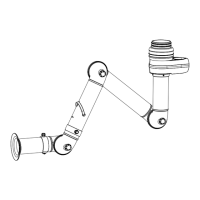
4.3Damper, swivel and link adjust-
ments
The links are factory set for normal working positions.
Always check and adjust the links so they will suit the
users preference.
See Figure14 (A).
1 Damper open.
2 Damper closed.
5Use
WARNING!Risk of personal injury
Always read Chapter2Safety before install-
ation, use, service, or troubleshooting of this
product.
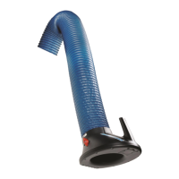
5.1Arm position
See Figure13. Always place the arm as close as pos-
sible to the source. When possible, place the arm side-
ways to the source for best capture, to avoid interfer-
ing with the work process, and to minimize the effect
of the cross draft. See Figure13 (A).
Always check that the airflow is sufficient in the hood
before work begins. Insufficient airflow can be due to:
• The fan impeller rotates in the wrong direction.
• Hood, arm or ducts are blocked.
For adjustments of damper, swivel and link, see Fig-
ure14 (A).
6Maintenance
WARNING!Risk of personal injury
Always read Chapter2Safety before install-
ation, use, service, or troubleshooting of this
product.
6.1Routine inspection and service
Follow the list in Chapter10Appendix B: Maintenance
checklist to routinely inspect, and repair or replace
worn and damaged parts on the inside and outside of
the product.
7Spare Parts
CAUTION!Risk of equipment damage
Use only N$e$d$e$r$m$a$n$ original spare parts and ac-
cessories.
Contact your nearest authorized distributor or
N$e$d$e$r$m$a$n$ for advice on technical service or
if you require help with spare parts. See also
w$w$w$.$n$e$d$e$r$m$a$n$.$c$o$m$.
7.1Ordering spare parts
When ordering spare parts always state the following:
• The part number and control number (see the
product identification plate).
• Detail number and name of the spare part (see
w$w$w$.$n$e$d$e$r$m$a$n$.$c$o$m$/$e$n$/$s$e$r$v$i$c$e$/$s$p$a$r$e$-$p$a$r$t$-
$s$e$a$r$c$h$).
• Quantity of the parts required.
8Recycling
The product has been designed for component mater-
ials to be recycled. Different material types must be
handled according to relevant local regulations. Con-
tact the distributor or$N$e$d$e$r$m$a$n$ if uncertainties arise
when scrapping the product at the end of its service
life.
18
 Loading...