1 Introduction Page 8
Stud welding units Operating manual Date: July 2021
INTRA 2100/1400 07.2021 / EN Rev.: A
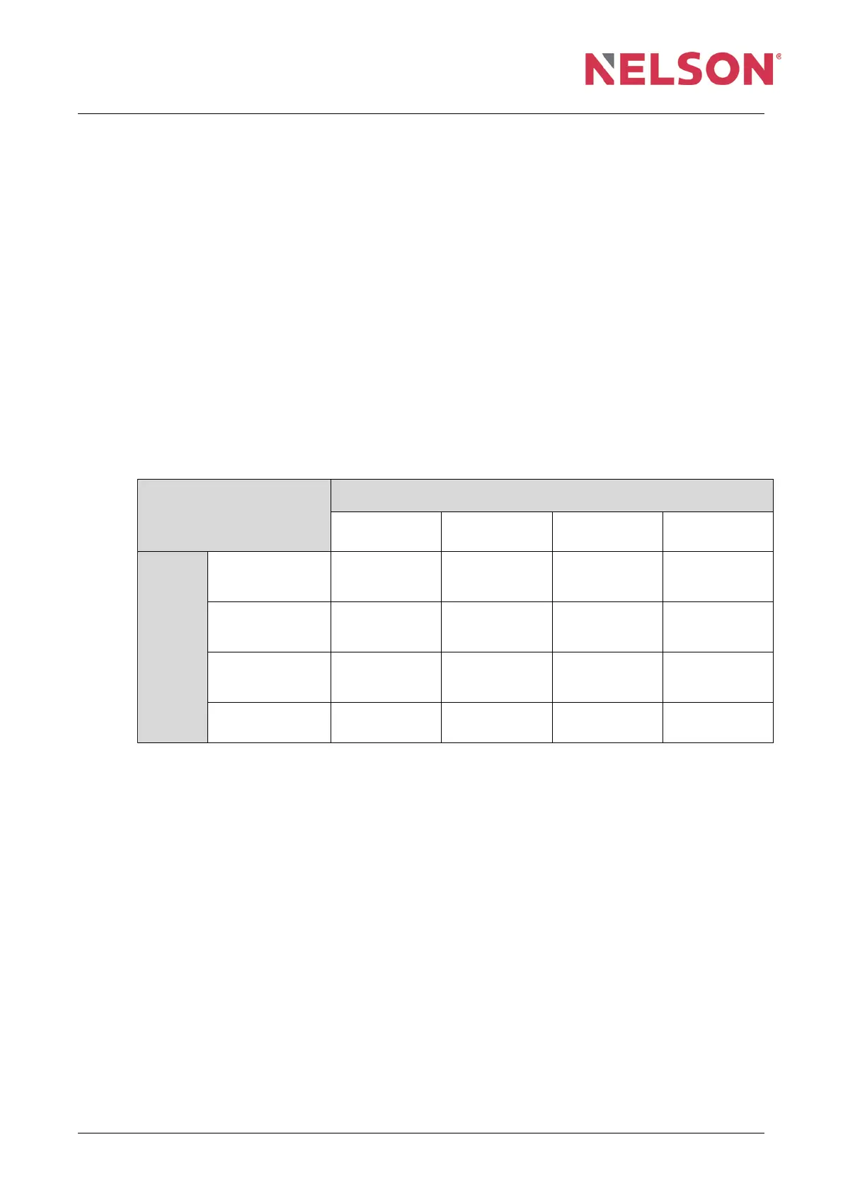
1.4 Material combinations
The material combinations listed in the table below have already been tested. The
weld angle for the material combinations is defined as follows:
a = suitable for any application, such as force transfer,
b = suitable with limitations for force transfer,
c = suitable with limitations only for heat transfer,
– = cannot be welded.
Explanation of superscript numbers:
1)
Up to 10 mm diameter and shielding gas in tub position (PA),
2)
Only during short cycle stud welding with drawn arc,
3)
Maximum yield strength R
eH
≤ 460 N/mm
2
.
Material
combination
Base material
EN ISO 15614-1
Groups 1 and 2
3)
EN ISO 15614-1
Groups 3 and 4
EN ISO 15614-1
Group 9
EN ISO 15614-2
Groups 21 and 22.1
Stud
S 235
4.8 (weld suitable)
16 Mo 3
a b b
2)
–
X 10 CrAl 18
X 10 CrAl 24
X 10 CrNiSi 25-4
c c c –
1.4301, 1.4303
1.4401, 1.4451
1.4571
b (a)
1)
b a –
EN AW-AlMg 3
EN AW AlMg 5
– – – b
Group 1: Steels with minimum yield stress of R
eH
≤ 360 N/mm
2
Group 2: Standardized or thermodynamically treated fine-grain structural
steels with a minimum yield stress of R
e
> 500 N/mm
2
Group 3: Annealed fine-grain structural steels with a minimum yield stress of
R
e
> 500 N/mm
2
Group 4: Steels with Cr max. 0.75%, Mo max. 0.6%, V max. 0.3%
Group 9: Austenitic stainless steels
Group 21: Pure aluminium with max. 1.5% impurities
Group 22.1: Non-curable AlMg alloys with ≤3.5% Mg content
Material combinations that are not listed in the table can be tested in the welding
laboratory. Contact your Tucker GmbH technical consultant.
*)
EN ISO 15614-1, 2: Specification and qualification of welding procedures for metallic materials – Welding
procedure test
 Loading...