Do you have a question about the NEP BDM-600 Series and is the answer not in the manual?
A brief welcome message and request for customer feedback on NEP products.
States compliance with NEC 2014, NEC 2017 article 690.12, and CEC 2015 section 64-218.
Instructions on how to use the manual and understanding warning symbols for safety.
Explains various safety and information symbols used in the manual and on the product.
Lists the specific NEP parts required for the BDM-600x installation kit.
Lists necessary additional parts and tools beyond the NEP kit for installation.
Explains the risk of lightning damage and the recommendation for surge protection.
Outlines the key steps involved in installing the BDM-600x Micro inverter system.
Details how to measure AC service and install the junction box for the AC branch circuit.
Provides instructions on how to mount the BDM-600x microinverters securely to the racking.
Explains the process of connecting the BDM-600x microinverters using the integrated trunk cable.
Details methods for safely grounding the BDM-600x microinverter system.
Describes grounding the system via the trunk cable and junction box connection.
Illustrates and explains grounding the BDM-600x through the racking system.
Details the sequence of actions to commission the system, including power activation.
Explains the importance of accurate serial number input for system configuration.
Describes the manual method of inputting inverter serial numbers directly via the gateway.
Explains how to use a barcode scanner to simplify serial number input into the gateway.
Details using a web browser to access the gateway for serial number input.
Guides new users on how to register for an installer account on the NEP website.
Instructions for homeowners to register an account to use NEP solar products.
Outlines pre-commissioning steps, including gateway connection and serial number entry.
Instructions on creating a new solar site on the NEP website, including site details.
Steps to verify site creation, access production data, and customize the site layout.
Details contacting NEP Support to schedule gateway commissioning and confirm setup.
Information on how to grant homeowners access to view module data.
Explains the LED indications for the microinverter when it is in standby mode.
Explains the LED indications for the microinverter when it is actively producing power.
Describes the LED indication for a grounding fault and error codes for various faults.
Details how LED lights indicate different error conditions and communication statuses.
Describes the LED behavior for general error modes, excluding grounding faults.
Explains the orange LED indication when the unit is not communicating with the gateway.
Describes the solid red LED indication for a grounding fault.
Provides a step-by-step guide to troubleshoot an inoperable BDM-600x/400 microinverter.
Details the safe procedure for disconnecting the BDM-600x from PV modules.
Instructions for securely mounting and connecting a replacement BDM-600x unit.
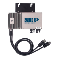
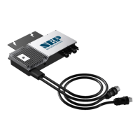
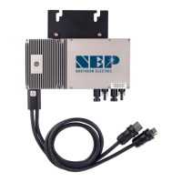
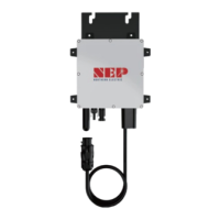
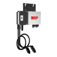
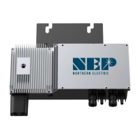
The Northern Electric Power (NEP) BDM-600x Microinverter is a cutting-edge clean energy technology designed for grid-tied solar photovoltaic (PV) systems. Its primary function is to convert the direct current (DC) produced by individual PV modules into alternating current (AC) that can be used by a home or business and fed back into the utility grid. This microinverter is part of NEP's comprehensive product line, which also includes rapid shutdown devices (RSD) and monitoring products, all aimed at providing state-of-the-art solar solutions.
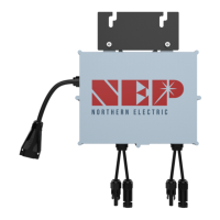
The BDM-600x Microinverter is designed for ease of installation and robust performance. It comes with an integrated trunk cable to simplify the AC connection process, featuring male and female connectors for daisy-chaining multiple microinverters to form a continuous AC branch circuit. This design streamlines the wiring process, reducing installation time and complexity. The microinverter is mounted directly to the PV module racking system, with specific instructions provided for proper placement and secure fastening to ensure optimal performance and longevity. It is crucial to follow the recommended spacing and avoid long-term exposure to direct sunlight in certain locations to prevent damage.
A key feature of the BDM-600x is its integrated ground protection circuit, with the grounding wire connected through the trunk cable and designed to be securely attached to the ground connector in the junction box. This ensures proper grounding of the microinverters and compliance with local electrical codes. The system can also be grounded through the racking itself, offering flexibility in installation.
For commissioning, the BDM-600x system involves several steps to ensure proper operation and data transmission. Once DC voltage from the PV modules is applied, the microinverter automatically powers on, and a status LED indicates its operational state. The LED light provides visual feedback: a two-second on/off cycle indicates standby, a one-second on/off cycle indicates power production, red signifies an error, orange indicates proper functioning but no communication with the gateway, and green indicates proper functioning and communication with the gateway. This visual feedback system helps installers quickly assess the microinverter's status.
The BDM-600x transmits performance data through power line communication (PLC) to a central gateway, such as the BDG-256. This gateway collects data from all connected microinverters, allowing for comprehensive monitoring of the PV system's performance. Inputting serial numbers for each microinverter into the gateway is a critical step in commissioning, which can be done manually using a stylus on the gateway's screen, via a USB barcode scanner, or through a web browser interface. The web browser method requires the gateway to be assigned an IP address and connected to WiFi, offering a convenient way to input serial numbers from a device like a phone or laptop. Accurate serial number input and site mapping are essential for effective monitoring and troubleshooting.
The NEP website plays a crucial role in managing the PV system. Installers can create accounts, register sites, and map the layout of the PV modules and microinverters. This online platform allows for monitoring energy production, viewing historical data, and customizing the site layout to accurately reflect the physical installation. Homeowners can also be granted access to a module view, enabling them to track their system's performance.
Maintenance of the BDM-600x Microinverter is designed to be straightforward, with a focus on troubleshooting and replacement rather than internal repair. The device contains no user-serviceable parts, and any troubleshooting methods that fail require the unit to be returned to the distributor for maintenance. Safety is paramount during maintenance, with strict warnings against disconnecting DC wire connectors under load and always disconnecting AC power before working with PV module wires. An opaque covering can be used to block sunlight from the module to ensure no current is flowing in the DC wires.
Troubleshooting an inoperable BDM-600x/400 involves a systematic approach, including verifying utility grid connections, checking voltage and frequency, confirming AC branch circuit interconnections, and ensuring PV module DC voltage is within range. The PLC signal quality can also be checked through the BDG-256 gateway interface to diagnose communication issues.
For replacement, the process involves securely mounting the new microinverter, connecting its AC cable to the neighboring units, completing the connection map, and connecting the PV modules. The serial number of the replacement unit must be updated in the BDG-256 gateway to ensure proper data transmission.
The BDM-600x microinverter incorporates multiple protective functions to ensure safe and reliable operation. These include protection against DC over/under voltage, AC over/under voltage, over/under frequency, over current, reverse DC polarity, and overload. It also features anti-islanding protection, which is crucial for grid safety. In the event of a fault, the microinverter will stop outputting power, and the fault message, in the form of a 16-bit error code, will be transmitted to the BDG-256 gateway for diagnosis. A solid red LED light indicates a grounding fault, prompting immediate attention.
Overall, the NEP BDM-600x Microinverter is a user-friendly, robust, and intelligent component of a modern solar PV system, designed for efficient energy conversion, comprehensive monitoring, and reliable operation with built-in safety features.
| Maximum Output Power | 600W |
|---|---|
| Cooling Method | Natural Convection |
| Output Frequency | 60Hz |
| Control Method | Maximum Power Point Tracking (MPPT) |
| Protection Features | Over Current Protection, Short Circuit Protection, Over Temperature Protection |