NESPACE48/3K Operation Manual
KE NESPACE KA Rectifier Control Unit Operation Manual English R 2016_07 V1_1
10 /21
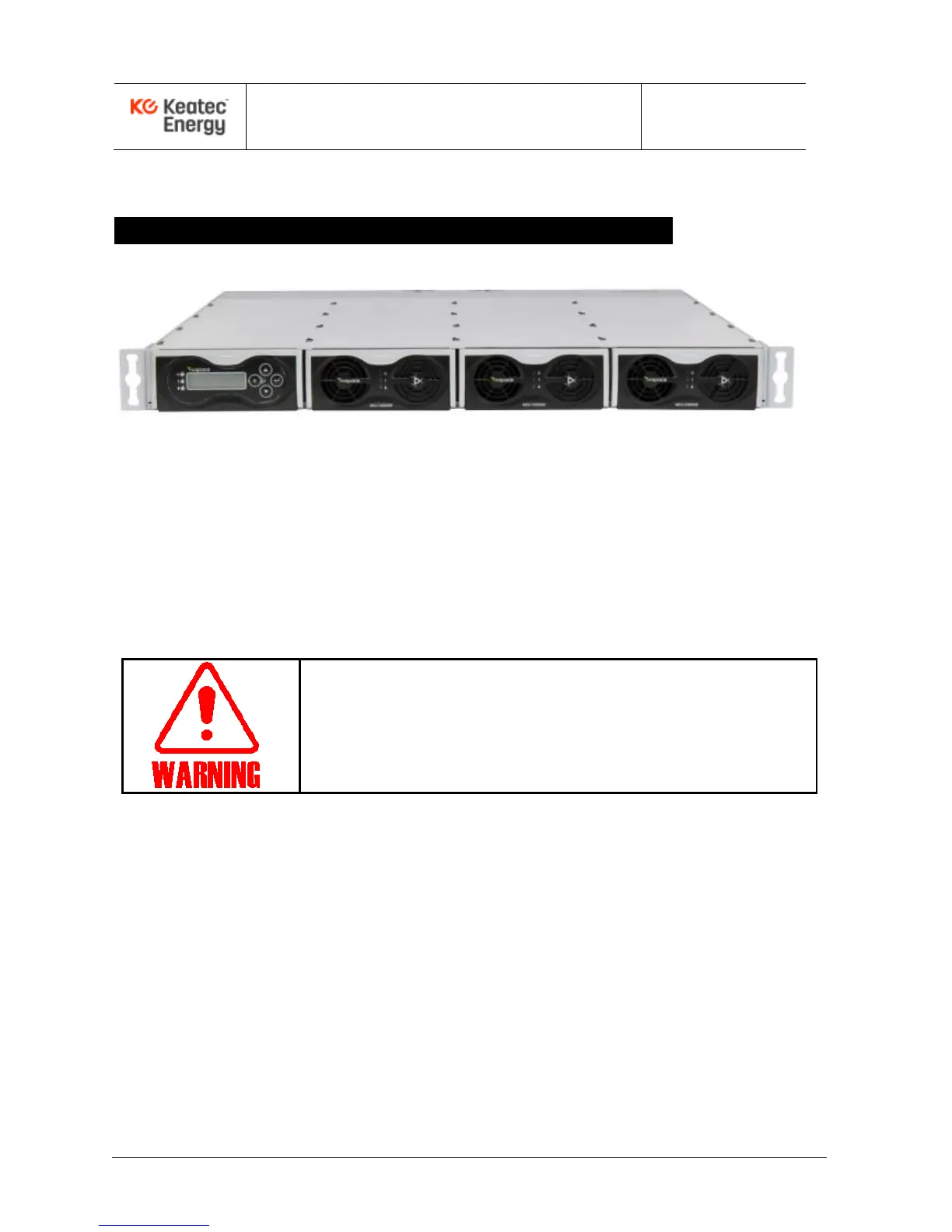
2 – NESPACE Shelf- Typical Installation & Cabling
Example of NESPACE48/3K Rectifier Modules installed into a CSPS-6K Shelf
Figure 2-1. Shelf with NESPACE rectifier modules installed
2.1 Preparation for Rack Installation
The rectifier modules should be installed into a shelf using an indoor cabinet/rack in a clean, dry
location, with at least 50cm spacing front and rear of the shelf to allow for unrestricted air flow.
2.2 Cabling to a shelf containing NESPACE48/3K Modules
● Focus on and follow safety procedures while installing rectifiers.
● Before cable installation, use a DVM to verify AC and DC voltages
are not present. Use tagout/lockout, as needed.
● Before starting any operation, carefully read the following directions.
Inputs and outputs of the NESPACE rectifier is typically connected through a shelf backplane,
PCB traces, filter networks, bus bars, terminals, connectors, and cables.
Pay attention to AC input Line/Load/GND and DC output connection polarities.
2.2.1 AC Input Connection
The AC input includes a lightning surge arrestor (10kA) within the backplane in a typical shelf.
AC input cables to the Rectifier Shelf should be physically separated from DC output cables as
much as possible to minimize EMI.
The AC 1ø3W input cable may be connected after AC voltage is verified to be OFF and
LOCKED-OUT. A typical 1U Rectifier Shelf configured with NESPACE48/3K rectifier modules is
shown in Figure 2.2, which shows the the Shelf’s rear-side power cable connections.