KE NESPACE KA Rectifier Control Unit Operation Manual English R 2016_07 V1_1
16 /21
If internal communication with the Control Unit fails, the ON LED slowly blinks.
4.2 FAIL LED (RED)
The FAIL LED is lit (RED) under one of the following conditions:
* When system is shut down due to the DC OV (OverVoltage) protection circuit.
* When system is shut down due to the OT (OverTemperature) protection circuit.
* When system is in a DC UV (UnderVoltage) due to an over-current limit condition.
* When the internal FAN has failed – FanFail (FF).
* When system shuts down due to the AC OV or AC UV exceeding rated spec limit.
* When output is not functioning or voltage falls below DC UV limit (for any reason).
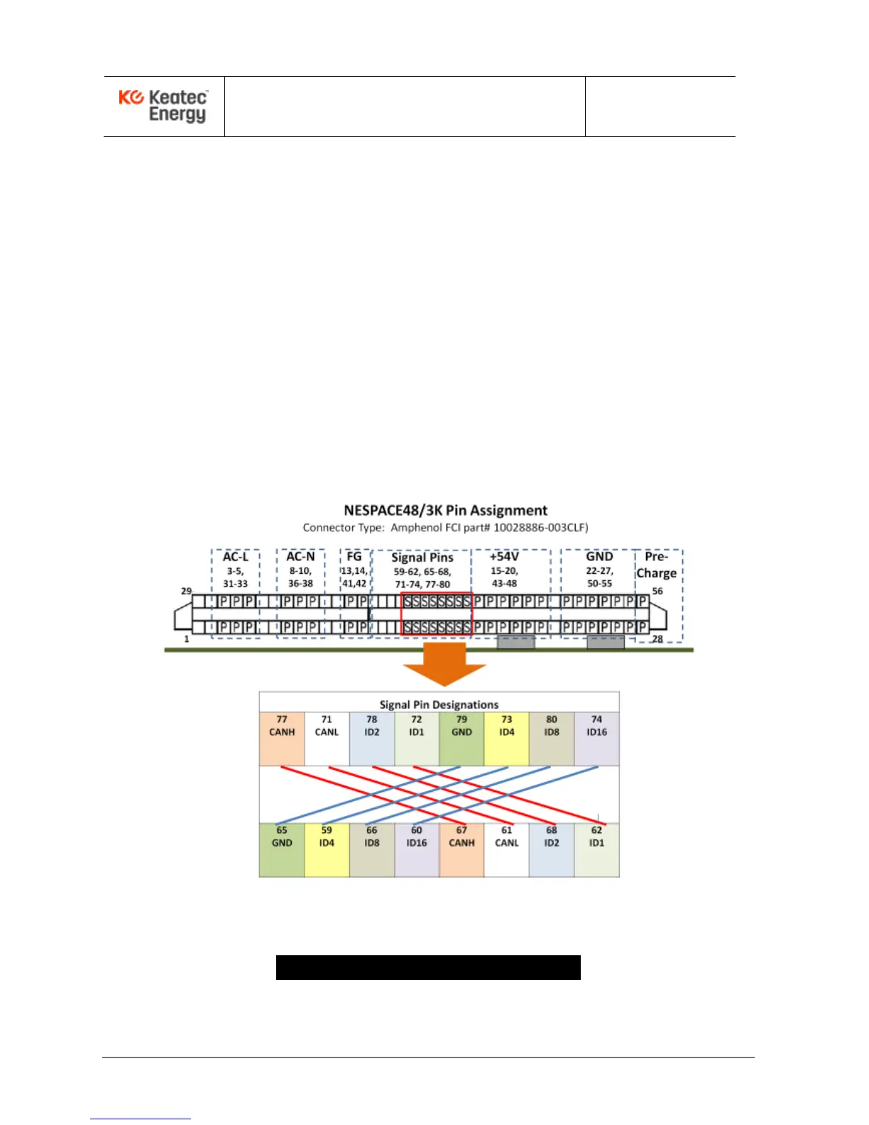
4.3 NESPACE48/3K Rectifier Module Connector Pinout
Figure 2-1. Rectifier Module Connector Pin Assignment
5 - Rectifier Module Operation