NESPACE48/3K Operation Manual
KE NESPACE KA Rectifier Control Unit Operation Manual English R 2016_07 V1_1
15 /21
3.4 Corrective Measures
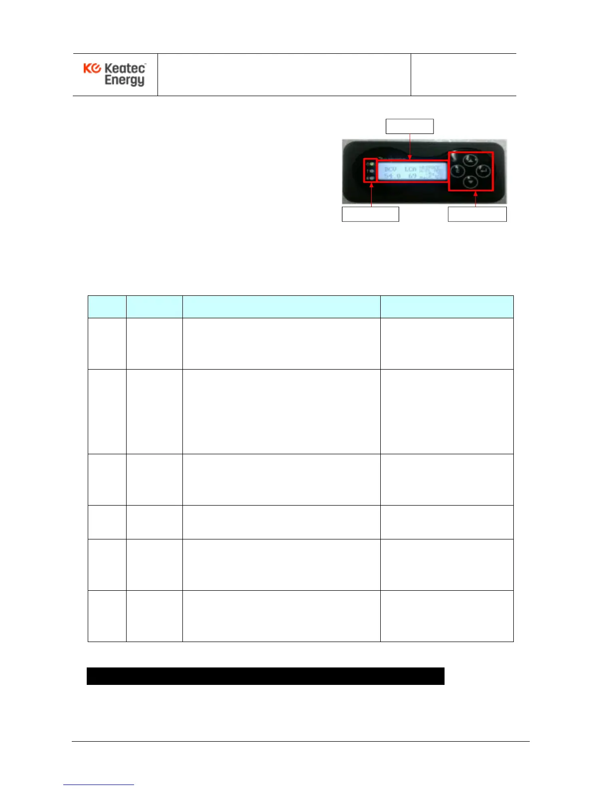
If the FAIL LED (red) is on while the
Rectifier Shelf is powered ON, the alarm
status will be displayed on the Control
Unit LCD window and the audible alarm
will sound. Check the alarm status and
take corrective measures, if needed.
LCD
WINDOW
LED
INDICATOR
SELECTION
BUTTON
Table 3-1 Corrective Actions per Alarm (optional, user defined)
AC High & Low voltage
Measure actual input voltage using the digital volt
meter. Verify input voltage UV, OV alarm settings.
AC UV : Under 174Vac
AC OV : Over 276Vac
Verify default setting of output voltage.
Verify output voltage UV,OV alarm settings.
Verify individual current of unit and check if load
sharing is working correctly (only for the case of
Under voltage fail).
DC OV : Over 58Vdc
DC UV : Under 47.5Vdc
If an inserted NESPACE rectifier module inserted
has any problem, remove and reinsert it. If it fails
again, replace the NESPACE rectifier module.
UNIT FAIL
(Default.#1~#2, Max #3)
Check details using a PC and the Debug port to
check the actual status of the alarm.
Rack. High Temp (80
℃
)
Rack. Sensor fail (open)
Check details using a PC and the Debug port to
check the actual status of the alarm. Check the
Digital input (Ext) Alarm cable
Digital input Alarm fail
(Default: Normally open)
If Control Unit has any problems, power the AC off
to the Shelf then remove and reinsert it. If it fails
again, replace the Control Unit.
* Alarm contact.type can be set arbitrarily to NO or NC(Normally Open or Normally Closed)
4 4 - NESPACE48/3K Rectifier Module Configuration
4.1 ON LED (GREEN)
The ON LED is lit (GREEN) when the Rectifier Module is in normal operation.