3
10/100/1000 Bypass Switch with Heartbeat
Product Diagrams
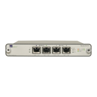
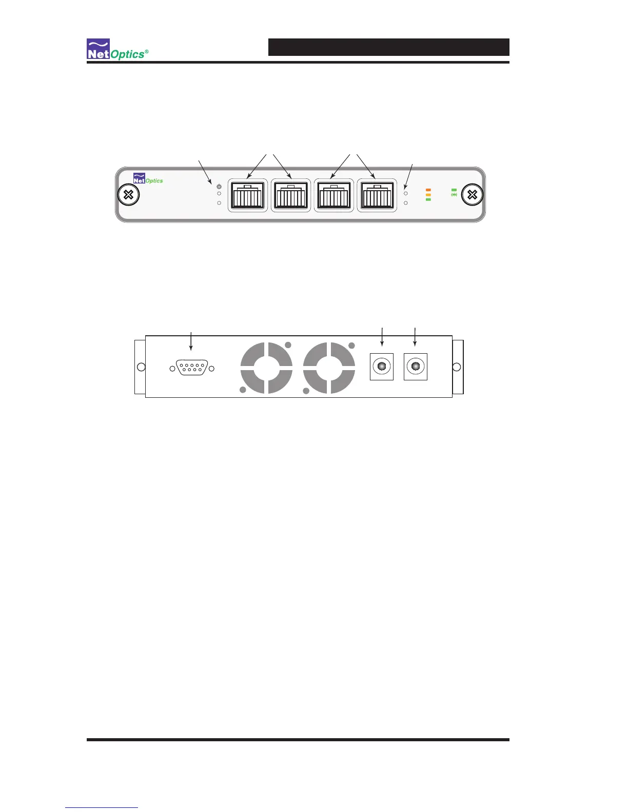
Figure 1: Front Panel
Figure 2: Rear Panel
LED Indicators
PWR 1/ PWR 2: Main and Redundant Power. If the Bypass switch is
deployed with both power supplies, both LEDs illuminate green when
power is connected to the bypass switch. An off power LED indicates that
the corresponding power supply is not functioning or not connected.
10/100/1000 Indicator: Located in the upper left-hand corner of the RJ45
connectors. If the Port is set to 10 Mbps, the LED illuminates orange. If
the Port is set to 100 Mbps, the LED illuminates yellow. If the Port is set to
1000 Mbps, the LED
illuminates green.
Link/Activity Indicator: Located in the upper right-hand corner of the
RJ45 connectors. If a good link is established, the LED illuminates a steady
green. When there is current activity on a good link, then the LED ashes.
•
•
•
 Loading...