4
10/100/1000 Bypass Switch with Heartbeat
Bypass Modes
The 10/100/1000 Bypass Switch with Heartbeat bypasses the attached in-line
device when one of three events occurs:
• Power loss to the switch
• Link failure
• Application failure
Two LEDs on the front of the 10/100/1000 Bypass Switch indicate whether
the bypass switch is bypassing the connected appliance or not. When the
Bypass ON indicator is illuminated, the bypass switch has not received the
heartbeat packet as expected. When the Bypass OFF indicator is illuminated,
the bypass switch is sending trafc through the attached in-line device.
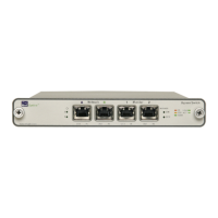
When the bypass switch is in Bypass Enabled (ON) mode, the switch circuitry
re-directs network trafc around the in-line appliance. In Bypass Enabled
mode Network Ports A and B are connected (see Figure 3).
Figure 3: Bypass Enabled
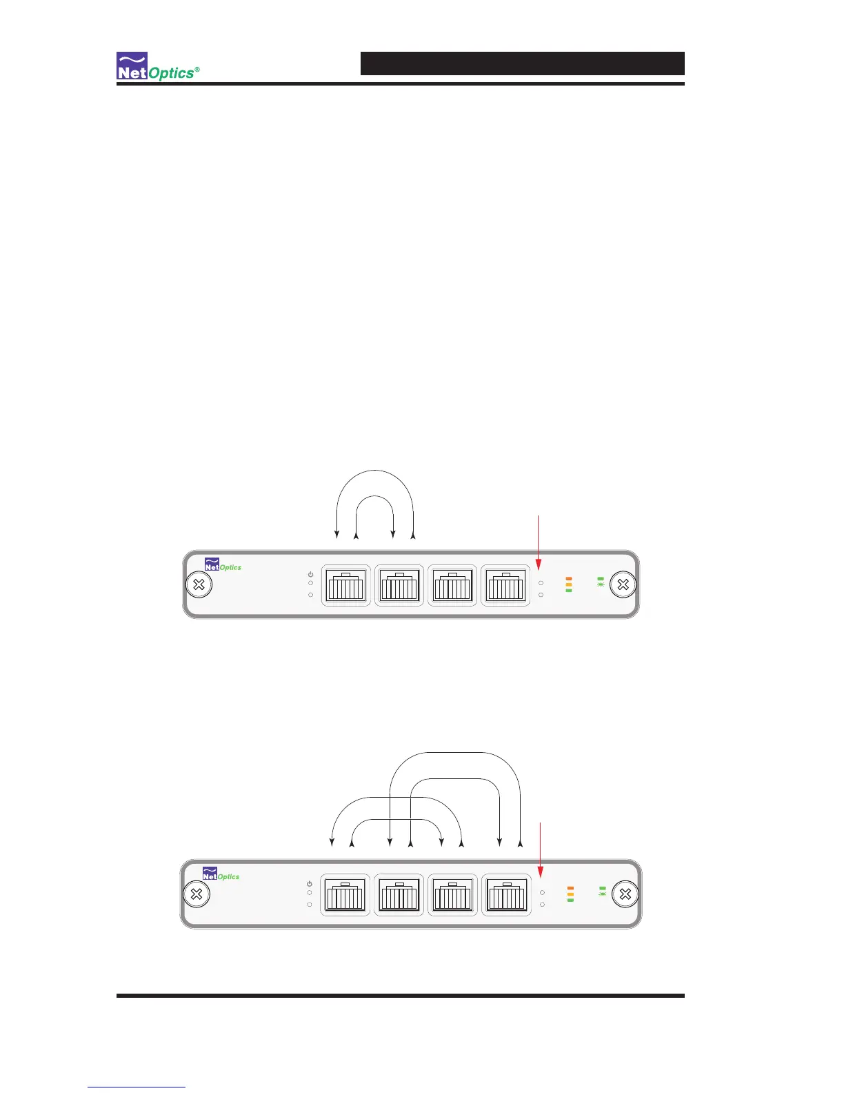
When the bypass switch is in Bypass Disabled (OFF) mode, the bypass switch
circuitry sends network trafc through the in-line appliance. In Bypass Dis-
abled mode, Network Port A is connected to Monitor Port C and Network Port
B is connected to Monitor Port D (see Figure 4).
Figure 4: Bypass Disabled
 Loading...