10
NETAFLEX™ 3G INSTALLATION MANUAL
DESCRIPTION
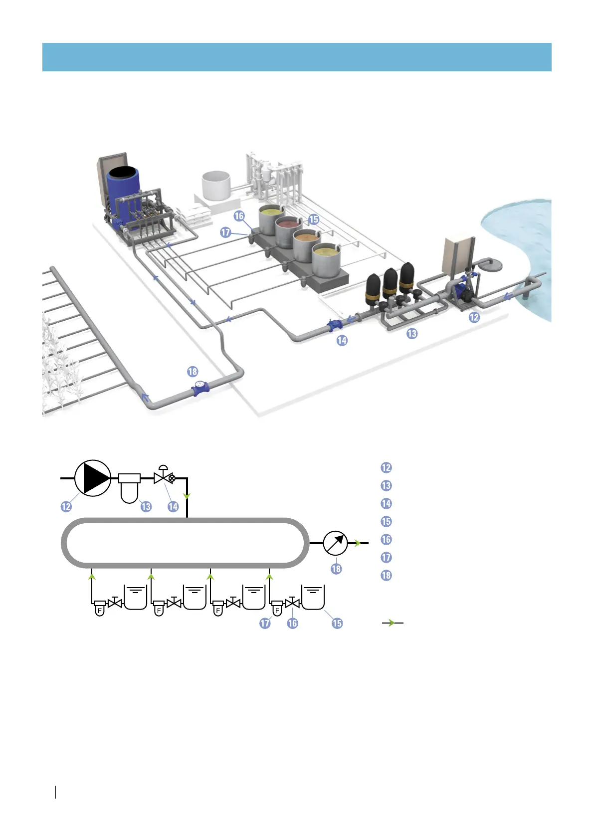
Typical installation overview
The drawing below represents a typical NetaFlex™ 3G infrastructure.
NetaFlex™ 3G
Infrastructure schematic diagram
Filling pump
Filling line filter
Pressure reducing valve
Fertilizer/acid stock tank
Manual valve (fertilizer)
Fertilizer/acid filter
Water meter
direction of flow
LEGEND
NETAFLEX
™
3G
 Loading...