12
NETAFLEX™ 3G INSTALLATION MANUAL
ON-SITE PREPARATIONS
D
d
X
1
X
2
X
3
H
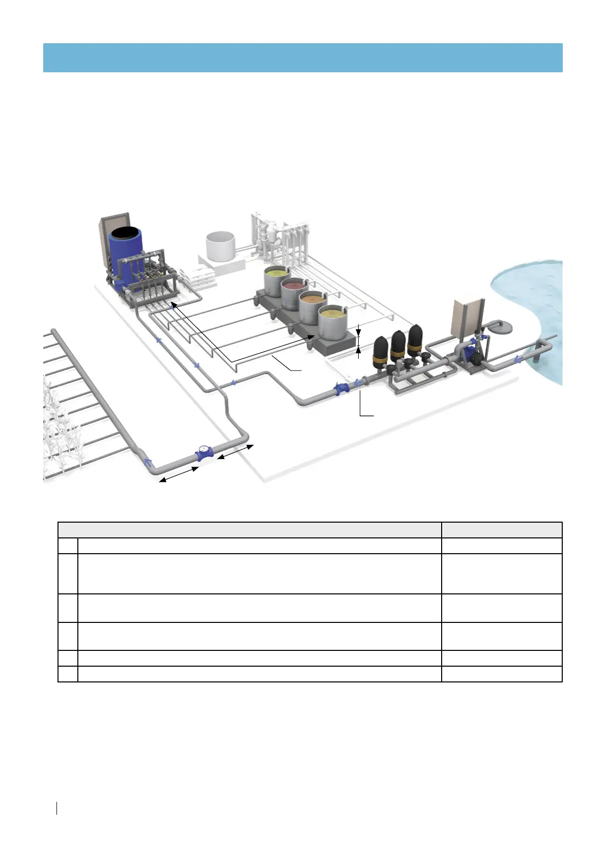
Description Required
proportions
D Filling line - pipe diameter
d Fertilizer/acid lines - pipe diameter:
• 32 mm (1¼") for dosing channels of up to 400 l/hr (106 GPH)
• 40 mm (1½") for dosing channels of over 400 l/hr (106 GPH)
X
1
Length of the pipe upstream from the water meter to the adjacent corner
• Pipe must be straight
10 x D
X
2
Length of the pipe downstream from the water meter to the adjacent corner
• Pipe must be straight
5 x D
X
3
Length of fertilizers or acid lines
Max. 10 meter (33 feet)
H Elevation of the fertilizer/acid tanks Min. 30 cm (12")
Infrastructure required proportions
Hydraulic infrastructure preparation
Before performing the infrastructure installation, consult Typical installation overview, page 12.
Required proportions
To enable optimal operation of the
NetaFlex™ 3G
, piping must be installed while maintaining the following
proportions.
NetaFlex™ 3G
Filling line flow rate and pressure requirements
In order to enable the NetaFlex™ 3G operation, the following requirements must be met.
• Source water should enter the NetaFlex™ 3G at a flow rate equal to the maximum flow rate required
for the field.
If the flow rate at the inlet of the NetaFlex™ 3G is insufficient, the low level switch will be activated
and the NetaFlex™ 3G operation will be stopped.
 Loading...