16
NETAFLEX™ 3G INSTALLATION MANUAL
INSTALLATION
Unpacking and placement
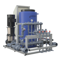
Check the ShockWatch label attached to the
packaging and ensure the indicator is white.
If the indicator is red - act according to the instruction
on the ShockWatch label.
Place the NetaFlex™ 3G package close to the irrigation
system using forklift.
Gently open the packaging.
Remove the 4 screws and bolts connecting the
NetaFlex™ 3G to the wooden pallet.
Remove plastic cover from controller (if existing).
Place the NetaFlex™ 3G in its position.
Adjust the legs so that the NetaFlex™ 3G is steady.
Hydraulic installation
WARNING
When handling fertilizers, acid and other chemicals, always use protective equipment,
gloves and goggles.
NetaFlex™ inlet/outlet connection
Connect the appropriate pipes to the inlet and the outlet of the NetaFlex™ 3G
(see Location of inlet, outlet and fertilizer/acid line connectors, page 13).
Two types of connectors are supplied
System pump
CM10 CM15 CM25 CR32 CR45 CR64
PVC, adaptor union - glue connector (installed)
63 mm 75 mm 90 mm
BSP or NPT nipple - male thread connector (supplied)
2" 2.5" 3"
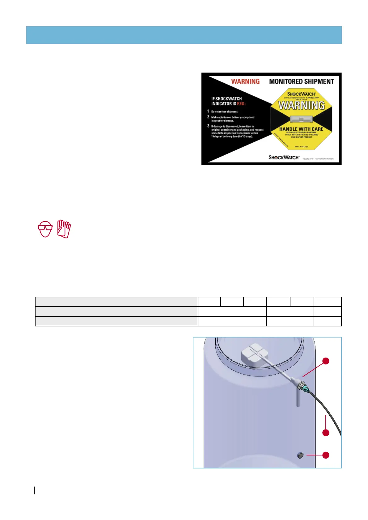
Float valve location
The float valve can be installed at two locations:
• Top location for 200 liter solution (as supplied)
• Bottom location for 100 liter solution
(supplied sealed with a rubber plug)
To shift the float valve location
• Remove the
rubber plug [A] from the other location.
• Disconnect the
controll tube [B] from the float valve.
• Disconnect the float valve
[C]
.
• Insert the rubber plug in its stead.
• Install the float valve at the other location.
• Connect the controll tube.
• After activation, check for leaks and fix if required.
A
B
C
 Loading...