UPSIDE-DOWN MICRO-EMITTERS HANDBOOK
15
C. Maximum length of distribution pipe
When planning an irrigation system, it is of utmost importance not to exceed the maximum possible
length of distribution pipes to avoid a severe reduction of working pressure and in certain cases, irrigation
uniformity, i.e. efficiency, consequently resulting in a lower yield.
Various factors influence the maximum possible length of distribution pipes:
• Emitter flow rate
• Internal diameter of the distribution pipe (ID)
• Internal texture (roughness) of the distribution pipe (C)
• Distance between emitters on the distribution pipe
• Topographic slope of the distribution pipe
• Pressure at the inlet of the distribution pipe
The calculation of the maximum possible length of a distribution pipe is not a straightforward process. It
is dependent on various factors that interact in a non-linear manner. The result of the combination of the
different factors is not intuitively predictable (as demonstrated in the examples below).
The maximum possible length of a distribution pipe is reached when there is a 20% difference between
the highest pressure of the micro-sprinkler/emitter head and that, which receives the lowest pressure
along the distribution pipe (a 20% pressure difference corresponds to a 10% flow rate difference, which is
the accepted maximum for defining uniform irrigation).
The selection of the diameter of a distribution pipe must be based on the required flow rate. This factor
has the greatest influence on the maximum possible length of the distribution pipe.
EXAMPLE
Max. distribution pipe length at different slopes - 10% flow rate loss
Where:
Pipe
PE 20/4
ID 17.0 mm
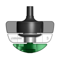
Emitter
SpinNet™
Nominal flow rate 70 l/h
Head pressure 2.5 bar
Slope
Distance between emitters (m)
1.0 2.5 5.0
Max. distribution pipe length (m)
Uphill 1% 39 70 105
Flat terrain 0 40 73 115
Downhill -1% 41 75 120
D. Head loss in the hanging micro-tube and accessories
Since correct planning requires the consideration of the pressure needed at the micro-sprinkler/emitter
head, the head loss in the hanging micro-tube and accessories cannot be ignored.
The head loss in the hanging micro-tube and accessories is defined by the following factors:
•
Friction loss
The friction loss inside the hanging micro-tube and accessories depends on:
• The flow rate
• The internal diameter (ID) of the hanging micro-tube
• The length of the hanging micro-tube
• The internal texture (roughness) of the hanging micro-tube and accessories
• The internal design of each accessory (e.g. AD valve)
MICRO-SPRINKLER/EMITTER SELECTION