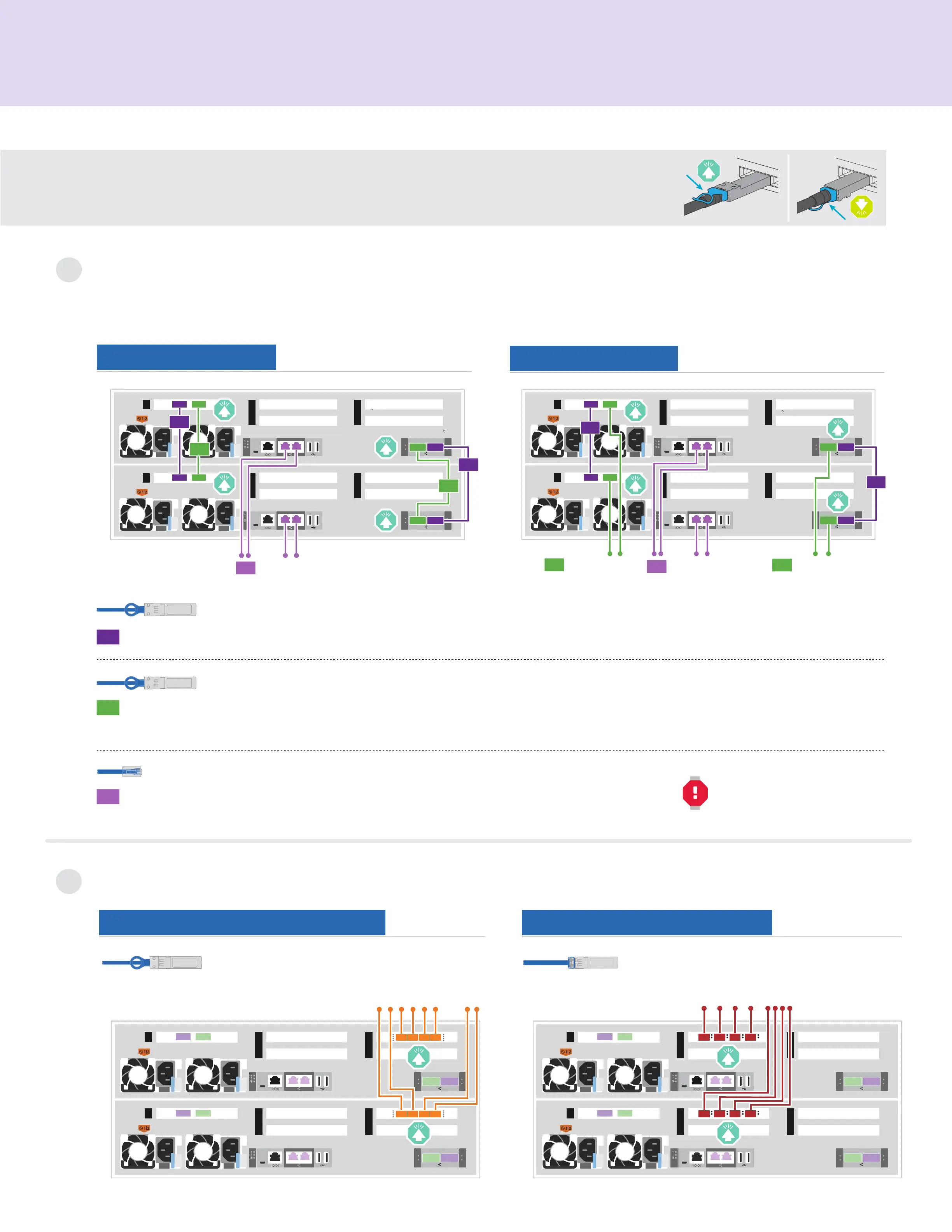
Cable controllers | Stage 2
Cable the controllers for a switchless or switched cluster
See your network administrator for help connecting to your switches.
Note: As you insert the connector, you should feel it click into place; if you do not feel it click, remove it, turn it around and try again.
1
Attention: Be sure to check the illustration arrow for the proper cable connector pull-tab orientation.
Note: To unplug a cable, gently pull the tab to release the locking mechanism.
Switched cluster
Switchless cluster
Connect port e1b to port e1b and port e0b to port e0b (HA interconnect only).
Switchless cluster Connect port e1a to port e1a and port e0a to port e0a.
Switched cluster Connect port e1a of each node and port e0a of each node to the cluster interconnect switches.
Cable the e0M port and BMC ports to the management switches.
3
Ethernet cables
1
2
100 GbE QSFP28 copper cables
100 GbE QSFP28 cables
DO NOT plug power cords into
the power source at this point.
Host network options
2
Option 2: FC host networkOption 1: 25 GbE host network
Cable ports e2a through
e2d to the host network.
SFP optical cables
Cable ports e4a through e4d
to the host network.
10 GbE SFP copper cables
1
4
5
2
3
1
4
5
2
3
1
1
2
2
To management
network switches
3
e1b
e0b
e0b
e0a
e0a
e1b
e1a
e1a
e0M BMC
e0M BMC
Controller AController B
1
4
5
2
3
1
4
5
2
3
To 10 GbE host
network switches
D C B A
D C B A
Controller AController B
1
4
5
2
3
1
4
5
2
3
To fibre channel switches
D C B A
D C B A
Controller AController B
1
4
5
2
3
1
4
5
2
3
1
1
To management
network switches
3
2
To cluster
interconnect
switches
2
To cluster
interconnect
switches
e0b
e0b
e0a
e0M BMC
e0M BMC
e0a
e1b e1a
Controller AController B
e1b e1a