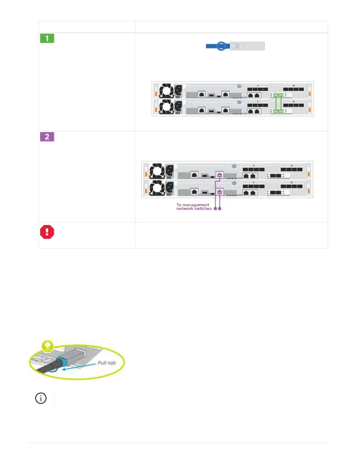
Step Perform on each controller
Cable the cluster interconnect ports to each other with the 25GbE
cluster interconnect cable
:
• e0c to e0c
•
e0d to e0d
Cable the wrench ports to the management network switches with the
RJ45 cables.
DO NOT plug in the power cords at this point.
2. To complete setting up your system, see
Step4: Completing system setup and configuration.
Option 2: Cable a switched cluster
All ports on the controllers are connected to switches; cluster interconnect, management,
Fibre Channel, and data or host network switches.
Contact your network administrator for information about connecting the system to the switches.
Be sure to check the illustration arrow for the proper cable connector pull-tab orientation.
As you insert the connector, you should feel it click into place; if you do not feel it click, remove
it, turn it around and try again.
1. Use the animation or the step-by step instructions to complete the cabling between the controllers and to
the switches:
188
 Loading...