Installation
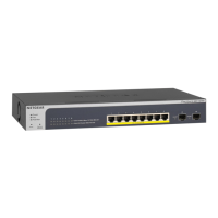
ProSAFE 8-Port Gigabit Smart Managed Switch
with PoE+ and 2 SFP Ports
GS510TLP and GS510TPP
Configure the Switch With a Static IP Address
Note: If your network uses a DHCP server, this section does not apply.
Go directly to Connect the Switch to a Network.
If you are using static IP addresses in your network, configure the switch IP
address before you connect the switch to a network.
1. Configure a computer with a static IP address in the 192.168.0.x subnet.
2. Plug the switch into a power outlet and connect your computer to the
switch using an Ethernet cable.
3. Open a web browser and enter 192.168.0.239 in the address bar.
The default IP address of the switch is 192.168.0.239.
A login page displays.
4. Enter password for the password.
The System Information page displays.
5. Select System > Management > IP Configuration.
The IP Configuration page displays.
6. Select the Static IP Address radio button.
7. Enter the static IP address, subnet mask, and default gateway IP address
that you want to assign to the switch.
8. Click the Apply button.
Your settings are saved.
Connect the Switch to a Network
1. Connect PoE (or non-PoE) devices to the RJ-45 PoE network ports on the
switch front panel.
Use Category 5e (Cat 5e) Ethernet cables terminated with RJ-45
connectors to make 1-Gigabit connections.
2. Connect an RJ-45 port or SFP port on the switch to a network that
includes a DHCP server.
If you use an SFP port, you must insert an SFP transceiver module that you
can purchase from NETGEAR.
3. Power on the switch and wait two minutes.
Package Contents
• NETGEAR ProSAFE® Smart Managed Switch GS510TLP or GS510TPP
• Rubber footpads for tabletop installation
• AC power cord (localized to country of sale)
• 19-inch rack-mount kit for rack installation
• Resource CD
Check the PoE Status
Model GS510TLP can supply up to 30W PoE+ (IEEE 802.3at) to each port,
with a maximum PoE power budget of 75W across all active PoE+ ports.
Model GS510TPP can supply up to 30W PoE+ (IEEE 802.3at) to each port,
with a total maximum PoE power budget of 190W across all active PoE+ ports.
The PoE Max LED indicates the status of the PoE budget on the switch:
• O. Sucient (more than 7W of) PoE power is available.
• Solid amber. Less than 7W of PoE power is available.
• Blinking amber. At least once during the previous two minutes, less than
7W of PoE power was available.
Configure the Switch
You can configure the switch either by using a computer’s web browser or by
installing the Smart Control Center Utility (see Smart Control Center Utility) on
your Windows-based computer.
Web Browser Access
1. For initial configuration, open a web browser on a computer that is on the
same network and subnet as the switch and enter the switch’s IP address.
If you are unsure how to determine the IP address of the switch, you can
use the Smart Control Center Utility.
A login page displays.
2. Enter password for the password.
PoE access points
PoE VoIP phone
Switch
Network
Internet
Sample connections