© NETGEAR, Inc., NETGEAR and the NETGEAR Logo
are trademarks of NETGEAR, Inc. Any non‑NETGEAR
trademarks are used for reference purposes only.
Specications
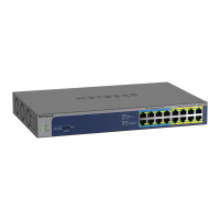
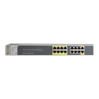
Specication Model GS516UP Model GS524UP
RJ-45ports 16GigabitEthernetfor1Gbps,
100Mbps,and10Mbps.
24GigabitEthernetfor1Gbps,
100Mbps,and10Mbps.
PoE++ports 8(ports1–8) 16(ports1–16)
PoE+ports 8(ports9–16) 8(ports17–24)
MaximumPoEbudget 380Wfortheentireswitch 480Wfortheentireswitch
ACpowerinput 100–240V~50/60Hz,8–4A 100–240V~50/60Hz,8–4A
Dimensions(WxDxH) 13.0x8.2x1.7in.
(330x207x43mm)
15.4x8.7x1.7in.
(390x220x43mm)
Weight 5.73lb(2.6kg) 6.83lb(3.1kg)
Operatingtemperature 32–122°F(0–50°C)
Operatinghumidity 10%–90%relativehumidity,noncondensing
Compliance FCCclassA,UL62368-1,CB,CELVD,CEclassA,VCCIclassA,RCMclassA,
KC,BSMI
Support and Community
Visitnetgear.com/supporttogetyourquestionsansweredandaccessthelatest
downloads.
YoucanalsocheckoutourNETGEARCommunityforhelpfuladviceat
community.netgear.com.
Regulatory and Legal
SiceproduitestvenduauCanada,vouspouvezaccéderàcedocumentenfrançais
canadienàhttps://www.netgear.com/support/download/.
(IfthisproductissoldinCanada,youcanaccessthisdocumentinCanadianFrenchat
https://www.netgear.com/support/download/.)
ForregulatorycomplianceinformationincludingtheEUDeclarationofConformity,visit
https://www.netgear.com/about/regulatory/.
Seetheregulatorycompliancedocumentbeforeconnectingthepowersupply.
ForNETGEAR’sPrivacyPolicy,visithttps://www.netgear.com/about/privacy-policy.
Byusingthisdevice,youareagreeingtoNETGEAR’sTermsandConditionsat
https://www.netgear.com/about/terms-and-conditions.Ifyoudonotagree,returnthe
devicetoyourplaceofpurchasewithinyourreturnperiod.
Donotusethisdeviceoutdoors.ThePoEsourceisintendedforintrabuildingconnection
only.
PoE++Mode DIPSwitch
Position
Ports1–4 Ports5–8 Ports9–12
(GS524UPOnly)
Ports13–16
(GS524UPOnly)
802.3bt Up Default Default Default Default
pre-802.3bt Down Optional Optional Optional Optional
Forinformationaboutwhichmodetoselect,consultthedocumentationthat
camewiththepowereddevice(PD).Ifyouarenotsure,keepthedefaultmode.
However,ifthePDdoesnotpowerup,settheDIPswitchtothepre-802.3btmode.
PoE considerations
ThePoEpowerthattheswitchsuppliestopowereddevices(PDs)isprioritized
inascendingportorder.IfthepowerrequirementsfortheattachedPDsexceed
thetotalpowerbudgetoftheswitch,thePDonthehighest-numberedport
isdisabledtomakesurethatthePDsconnectedtothehigher-priority,lower-
numberedportsaresupportedrst.
APDlistedasan802.3btPoE++powereddevicedoesnotnecessarilyrequire
themaximumpowerlimitofthespecication.ManyPDsrequirelesspower,
potentiallyallowingallPoE++andPoE+portstobeactivesimultaneously.
Thefollowingtableshowsthestandardpowerrangescalculatedwiththe
maximumcablelengthof328feet(100meters).
Device
Class
CompatiblePoE
standard
ClassDescription MaximumPower
Suppliedbythe
Switch
Power
Deliveredto
thePD
0 PoE,PoE+,andPoE++ Defaultpower(full) 0.44W 0.44W–12.95W
1 PoE,PoE+,andPoE++ Verylowpower 4.0W 0.44W–3.84W
2 PoE,PoE+,andPoE++ Lowpower 7.0W 3.84W–6.49W
3 PoE,PoE+,andPoE++ Midpower 15.4W 6.49W–12.95W
4 PoE+andPoE++ Highpower 30.0W 12.95W–25.5W
5–6 PoE++only Ultrapower 45.0W 25.5W–51W
IfadevicereceivesinsufcientPoEpowerfromtheswitch,considerusinga
shortercable.
PoE troubleshooting
HerearesometipsforcorrectingPoEproblemsthatmightoccur:
• IfthePoEMaxLEDissolidyellow,disconnectoneormorePoEdevicesto
preventPoEoversubscription.
• Foreachpowereddevice(PD)thatisconnectedtotheswitch,theassociated
PoELEDontheswitchlightssolidgreen.IfthePoELEDlightssolidyellow,a
PoEfaultoccurredandPoEhaltedbecauseofoneoftheconditionslistedin
thefollowingtable.
PoEFaultCondition PossibleSolution
APoE-relatedshortcircuitoccurredontheport.
Theproblemismostlikelywith
theattachedPD.Checkthe
conditionofthePD,orrestart
thePDbydisconnectingand
reconnectingthePD.
ThePoEpowerdemandofthePDexceededthemaximum
levelthattheswitchpermits.Themaximumlevelis15.4Wfor
aPoEconnection,30WforaPoE+connection,and60Wfora
PoE++connection.
ThePoEcurrentontheportexceededtheclassicationlimit
ofthePD.
ThePoEvoltageoftheportisoutsidetherangethatthe
switchpermits
Restarttheswitchtoseeifthe
conditionresolvesitself.
Mount the switch in a rack
Werecommendthatyouusethebracketsandscrewsthatcamewiththeswitch.
1. Attachthesuppliedmountingbracketstothesideoftheswitch.
2. Insertthesuppliedsmallscrewsthrougheachbracketandintothebracket
mountingholesintheswitch.
3. TightenthescrewswithaNo.1Phillipsscrewdrivertosecureeachbracket.
4. Alignthemountingholesinthebracketswiththeholesintherack,andinsert
theprovidedpan-headscrews(youcanchooseamongtwotypesof
pan-headscrews)withnylonwashersthrougheachbracketandintotherack.
5. TightenthescrewswithaNo.2Phillipsscrewdrivertosecuremounting
bracketstotherack.
May2020
 Loading...