Do you have a question about the NETGEAR ProSafe JGS524 and is the answer not in the manual?
Choose a flat horizontal surface or 19-inch rack, ensuring it is not in direct sunlight or near vents.
Connect Cat 5e Ethernet cables (<100m) and mount the switch on a flat surface or in a rack.
Inspect equipment, verify cable installation, routing, and secure mounting before applying power.
Use Phillips head screws to fasten mounting brackets to the switch sides securely.
Align brackets with rack holes and use pan-head screws to fasten the switch to the rack.
Ensure the power cord is securely connected to the switch and a functioning power outlet.
Check cable connections, device power, NIC installation, and cable length (<100 meters).
Details IEEE 802.3 standards compatibility and RJ-45 Ethernet interface specifications.
Lists power supply requirements, consumption, physical dimensions, and weight.
Covers frame filter/forward rates, latency, and jumbo frame support.
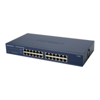
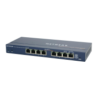
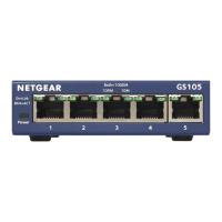
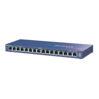
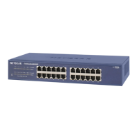
This document describes the ProSafe 16-port or 24-port Gigabit Switch, models JGS516 V2 and JGS524 V2, from NETGEAR. This device functions as a network switch, allowing multiple Ethernet devices to connect and communicate within a local area network. It supports various connection speeds, including 10 Mbps, 100 Mbps, and 1000 Mbps (Gigabit Ethernet), facilitating fast data transfer, especially for large files, with speeds up to 2000 Mbps due to its full-duplex Gigabit Ethernet capabilities. Depending on the model, the switch provides either 16 or 24 Gigabit Ethernet ports, enabling connectivity for a range of devices such as computers, file servers, printers, routers, and other network switches or hubs. The device is designed for ease of use and flexibility in network setup.
For usage, the switch offers straightforward installation. Users can choose to place the switch on a flat horizontal surface or mount it in a standard 19-inch rack. When placing on a flat surface, the switch comes with four self-adhesive footpads that should be applied to the concave spaces on the bottom of the device. These footpads help cushion the switch against shock and vibrations. For rack mounting, the provided rack-mount kit should be used. This involves fastening mounting brackets to the sides of the switch with Phillips head screws, then aligning the brackets with the rack holes and securing them with pan-head screws and nylon washers.
The switch automatically configures its ports based on the type of Ethernet cable connected, supporting both straight-through and crossover cables. This auto-sensing feature simplifies network setup by eliminating the need for specific cable types for different connections. Each Ethernet cable connected to the switch should be an enhanced Category 5 (Cat 5e) or higher, with RJ-45 connections, and must not exceed 328 feet (100 meters) in length.
Before applying power, users are advised to perform several checks to ensure proper and safe operation. These include a thorough inspection of the equipment, verification that all cables are correctly installed, and confirmation that cable routing prevents damage and safety hazards. Additionally, all equipment should be mounted securely, whether on a flat surface or in a rack.
The device's front panel features LEDs that serve as indicators for troubleshooting hardware problems. For instance, if the Power LED is off, it indicates that the switch is not receiving power. In such cases, users should check that the power cord is securely connected to both the switch and a functioning power outlet. If connected to a power strip or an outlet controlled by a light switch, it's important to ensure that the power strip or switch is in the "on" position.
If a Port LED is off for a connected device or stays on continuously, it suggests a hardware connection problem specific to that port. Troubleshooting steps include verifying that the cable connectors are securely plugged into both the switch and the connected device, and ensuring that the connected device itself is turned on. If the Ethernet cable is connected to a network interface card (NIC) or another Ethernet adapter, users should confirm that the card or adapter is correctly installed and functioning. As a general rule, the Ethernet cable length should also be checked to ensure it is less than 328 feet (100 meters).
For maintenance, the device is designed to operate within specific environmental conditions. It should not be placed in direct sunlight or near heating vents, and the location should not be cluttered or crowded. A minimum of 2 inches (5 cm) of clear space on all sides of the switch is recommended to ensure adequate ventilation, especially if the device is installed in a closet. These environmental considerations are crucial for the longevity and reliable performance of the switch. The device also includes an internal universal power supply, simplifying power management.
The switch is compliant with various electromagnetic and safety standards, including CE, FCC Class A, and UL, indicating its adherence to international safety and performance regulations. For further support and information, NETGEAR provides product updates and web support through its website. Registration of the product is strongly recommended to access telephone support services. Additionally, information regarding the GNU General Public License (GPL) and EU Declarations of Conformity is available online. Users are also cautioned against stacking equipment or placing it in tight spaces, drawers, or on carpets, emphasizing the importance of maintaining proper airflow around the device to prevent overheating and ensure optimal operation.
| Model | JGS524 |
|---|---|
| Category | Switch |
| Ports | 24 |
| Port Type | Gigabit Ethernet |
| Form Factor | Rack-mountable |
| Switching Capacity | 48 Gbps |
| Forwarding Rate | 35.7 Mpps |
| MAC Address Table Size | 8000 entries |
| Jumbo Frame Support | Yes |
| Energy Efficient Ethernet | No |
| Dimensions | 440 x 205 x 43 mm |