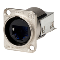
The NE8FDY-C6 etherCON Receptacle is a robust and versatile connector designed for professional audio, video, and data applications, ensuring reliable network connections in demanding environments. This assembly instruction details the steps for preparing cables, connecting the shield, separating and positioning wires, mounting the cable, fixing the wires, assembling the cover, connecting the screen, assembling the adapter, and finally, assembling the chassis. The design emphasizes ease of assembly and secure connections, making it suitable for both field installations and permanent setups.
Function Description:
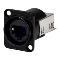
The NE8FDY-C6 etherCON Receptacle serves as a panel-mount connector for Ethernet cables, providing a ruggedized solution for standard RJ45 connections. Its primary function is to convert a standard RJ45 plug into a durable, lockable connection suitable for harsh environments where standard RJ45 connectors might be prone to disconnections or damage. It supports various cable types, including S-FTP, SF-UTP, and F-UTP, accommodating different shielding requirements. The receptacle ensures signal integrity and reliable data transmission by providing a secure and shielded connection. The assembly process is designed to ensure proper termination of the cable, including correct wire positioning according to TIA 568A or TIA 568B standards, and effective shielding to minimize electromagnetic interference (EMI). The locking mechanism, integrated into the adapter and chassis assembly, prevents accidental disconnections, which is crucial in live performance, broadcast, and industrial settings.
Usage Features:
The NE8FDY-C6 etherCON Receptacle offers several usage features that enhance its practicality and reliability.
- Cable Preparation Versatility: The initial cable preparation steps are designed to accommodate different cable constructions. Users begin by stripping the cable jacket, typically to a length that allows for proper wire management. For shielded cables (S-FTP, SF-UTP), the screen is then twisted, which is a critical step for maintaining shielding effectiveness. This flexibility ensures compatibility with a wide range of Ethernet cables commonly used in professional applications.
- Shielding Options: The receptacle supports various shielding configurations. For S-FTP and SF-UTP cables, the assembly includes steps for connecting the braided screen and foil shield, respectively, to the connector's housing, ensuring a continuous shield path. This is crucial for EMI/RFI protection, especially in environments with high electrical noise. The "Connect the screen" step involves hanging up the twisted screen and then cutting it to the appropriate length, ensuring good contact with the connector's metal housing.
- Wire Management System: A key feature is the integrated wire management system, which simplifies the process of positioning the individual wires. The system includes a sticker indicating the correct order of wires for both TIA 568A and TIA 568B standards. This visual guide helps prevent wiring errors, which are a common cause of network connectivity issues. Users insert the wires into designated positions, ensuring proper alignment before trimming.
- Cable Mount and Strain Relief: After positioning the wires, the cable is secured to the connector body using a cable tie. This step provides essential strain relief, preventing tension on the wire terminations when the cable is pulled or moved. The "Cable mount" step ensures that the cable is firmly attached, enhancing the overall durability of the connection.
- Secure Wire Fixing: The "Fix wires" step involves pressing down on the wire management system, which securely locks the individual wires into place and simultaneously trims any excess wire. This integrated trimming feature streamlines the assembly process and ensures a clean, professional termination.
- Robust Assembly Process: The assembly of the cover, adapter, and chassis is designed for a secure and interlocking fit. The "Cover assembly" involves snapping the cover onto the terminated wires. The "Assembly the adapter" step requires inserting the adapter until it snaps into place, providing the locking mechanism for the RJ45 plug. Finally, "Assembly the chassis" involves pressing down the chassis until it snaps in, completing the ruggedized enclosure. This multi-stage assembly ensures that all components are tightly integrated, contributing to the connector's overall strength and resistance to environmental factors.
- Grounding Option: The receptacle includes a "Grounding option" where a contact can be inserted if the screen needs to be connected to the front panel. This feature provides flexibility for system designers to implement specific grounding schemes, further enhancing EMI protection and system safety.
- Right-Angle Version Compatibility: The manual explicitly mentions that the working steps are largely the same for a right-angle version, with specific exceptions for Step B (Shielding) and Step G (Cover assembly). For the right-angle version, the reinforcement metal needs to be bent at a right angle, and the cable outlet must not be interrupted. This indicates the design's adaptability to different form factors without significantly altering the core assembly procedure.
- Locking Mechanism: The "Assembly the adapter" step highlights the "Insert until it snaps in" action, which is crucial for the etherCON's locking feature. This mechanism ensures that a standard RJ45 plug, when inserted into the adapter, is securely held in place, preventing accidental disconnections even under vibration or stress.
Maintenance Features:
While the NE8FDY-C6 etherCON Receptacle is designed for durability and long-term reliability, certain aspects contribute to its maintainability and longevity.
- Durable Construction: The robust materials and interlocking design of the chassis and adapter contribute to the connector's overall resilience. This minimizes the need for frequent replacement due to wear and tear, especially in high-use environments.
- Clear Assembly Instructions: The detailed, step-by-step instructions with clear illustrations serve as an excellent guide for proper assembly. Correct initial assembly is the most critical factor in ensuring the connector's long-term performance and minimizing maintenance needs. Improper assembly can lead to intermittent connections or premature failure, so adherence to the guide is a key preventative measure.
- Cable Strain Relief: The integrated cable mount with a cable tie provides effective strain relief. This prevents stress on the internal wire terminations, which are often the weakest point in a cable assembly. By protecting these critical connections, the strain relief feature significantly extends the lifespan of the cable and connector assembly, reducing the likelihood of signal loss or intermittent operation that would require troubleshooting or repair.
- Shielding Integrity: The emphasis on proper screen connection and grounding options ensures that the shielding effectiveness is maintained throughout the connector's life. A well-shielded connection is less susceptible to external interference, which can degrade signal quality and necessitate troubleshooting. By preventing such issues, the design contributes to lower maintenance requirements.
- Modular Design: The connector's assembly involves distinct components (cover, adapter, chassis). While not designed for field repair of individual internal components, this modularity simplifies the manufacturing process and ensures that each part contributes to the overall integrity. If a connector is damaged, it is typically replaced as a unit, but the robust design aims to minimize such occurrences.
- Standard Compliance: Adherence to TIA 568A/B wiring standards ensures compatibility with standard Ethernet networks and simplifies troubleshooting if connectivity issues arise. Technicians familiar with these standards can easily verify wiring configurations, which aids in diagnosing and resolving problems.
- Visual Inspection Points: During assembly, several steps involve visual checks, such as ensuring wires are correctly positioned according to the label and that components snap into place. These visual cues during installation help confirm proper assembly, reducing the chance of latent defects that might lead to future maintenance issues.
- Secure Locking Mechanism: The locking mechanism, once engaged, provides a highly secure connection. This prevents accidental disconnections that could lead to system downtime or require immediate intervention. The reliability of this lock contributes to the overall "set it and forget it" nature of the connector, reducing the need for constant monitoring or re-connection.
- "Please fix the cable additionally" Note: The final instruction to "Please fix the cable additionally" after chassis assembly is a crucial maintenance-related tip. This suggests securing the cable to the equipment panel or rack, further reducing strain on the connector itself and preventing movement that could lead to wear or damage over time. This proactive measure enhances the long-term stability of the entire connection.