4081 User Manual Issue 3
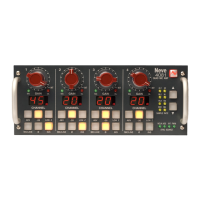
4081 unit ID dip switches
When remotely controlling more than one unit, the ID dip-switches on the
rear of the unit need to be set so that each unit on the chain responds to
the correct commands.
The first 3 switches from left to right are used to set the machine IDs from
1-8.
These switches are On when in the down position (the right-most switch
on this block puts the unit into 'Bootloader Mode' which allows the 4081
firmware to be updated. Please see page 24 for this procedure).
Unit ID Switch 1 Switch 2 Switch 3
1 Off Off Off
2On Off Off
3 Off On Off
4On On Off
5 Off Off On
6On Off On
7 Off On On
8On On On
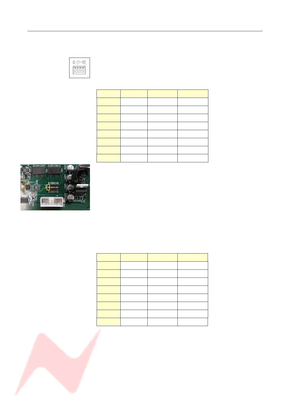
Where there are more than 8 units on the RS 485 chain, the IDs for units
greater than 8 are set using dip-switch 1 on the switch-block labelled
SW2 inside the unit (with the front of the unit to the left, this switch-block
is just above a white programming connector).
• With this switch in the down position, the unit will have an ID
between 1 & 8.
• With this switch in the up position, the unit will have an ID
between 9 & 16.
NB:
Switch 1 is On when in the up position.
Remove the lid to the unit, and set switch 1 to be ON, then set the
switches on the rear of the unit to the following:
fp
Unit ID Switch 1 Switch 2 Switch 3
9 Off Off Off
10 On Off Off
11 Off On Off
12 On On Off
13 Off Off On
14 On Off On
15 Off On On
16 On On On
If a unit's ID is changed, the 4081 must be switched off and on again for
the remote control software to be aware of the new ID number.
If the ID number is set incorrectly, a unit will either fail to respond or
multiple units will respond to a single command.
- 29 -
Front of unit
The switch-block will be covered
with a thin protective film which
should be removed first.